Getting started, Part names and functions – Kawai VPC1 User Manual
Page 4
Getting Started
Thank you for purchasing the Kawai VPC1.
This owner’s manual contains important information regarding the usage and
operation of the VPC1. Please read all sections carefully, keeping this manual
handy for future reference.
Part Names and Functions
1
POWER button
This button is used to turn the instrument on and off. The LED will be lit when
the power is turned on.
The status of the VPC1 will be indicated by the colour and appearance of the POWER
button LED as follows:
Instrument Status
Power button LED colour and appearance
Preset 1
Red
Preset 2
Orange
Preset 3
Green
Preset 4
Orange blinking
Preset 5
Green blinking
Updating VPC1
Red and Green blinking slowly (2 second intervals)
Updating error
Red and Green blinking rapidly (0.2 second intervals)
Power error
Red blinking
The VPC1 features a power saving function that can be used to automatically turn
off the instrument after a specified period of inactivity.
Please refer to the PDF manual of the VPC Editor Software for further information.
1.
2
3
4
5
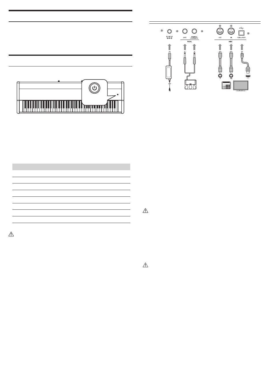
DC IN jack (12 V)
This jack is used to connect the included AC power adapter to the VPC1’s DC IN
jack.
Pedal jack
The jacks are used to connect the included Kawai pedal unit to the VPC1.
MIDI IN/OUT connectors
The jacks are used to connect the instrument to external MIDI devices (such as
other musical instruments or a computer) in order to send and receive MIDI data.
USB to Host connector
This port is use to connect the instrument to a computer using a USB ‘B to A’
type cable in order to send and receive MIDI data
The AC power adapter is required when connecting the VPC1 to a device/computer
using the MIDI connectors.
When connecting the VPC1 to a computer using a USB cable, the AC power adapt-
er is not required as power will be supplied through the computer’s USB connector.
This port is use to connect the instrument to a computer using a USB ‘B to A’ type
cable in order to send and receive MIDI data
However, in some cases the computer’s USB connector may be insufficient to pow-
er the VPC1 correctly. In this case, the POWER button LED will blink red, indicating
that the AC power adaptor is required.
If VPC1 update is not completed successfully, the POWER button LED will blink red
and green rapidly (0.2 second intervals).
In this case, please try to update the VPC1 again.
2.
3.
4.
5.