Procedure, Caution – Kleenmaid IC57 User Manual
Page 4
4
Procedure
7.
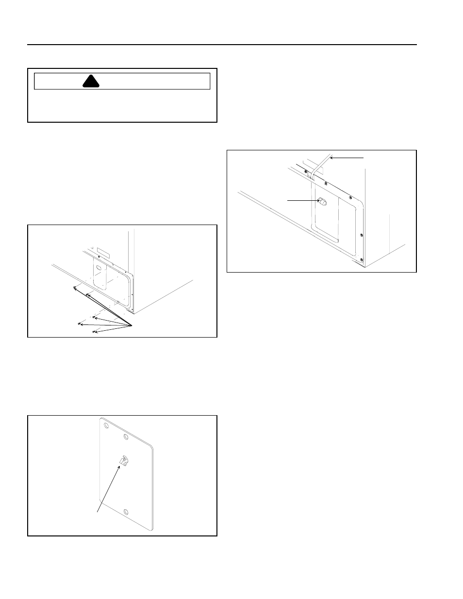
Connect wires to water valve. Place water valve on
mounting bracket. Insert screws into top 2 holes in
water valve cover plate and lower 2 holes in mounting
bracket. Tighten screws with a 6.35 mm (
1
/
4
") hex nut
driver.
8.
Replace back cover by placing cover on refrigerator
cabinet. Insert and tighten screws with a 6 mm hex
nut driver. Confirm elbow on water valve protrudes
through hole in back cover. Confirm plastic tubing is
routed through cutout section on top of back cover.
C
D
C. Plastic tubing.
D. Water valve elbow.
9.
Remove tape from end of copper tubing. Put end of
copper tubing into sink or bucket. Slightly turn on
water supply to refrigerator. Water will be under
considerable pressure. Allow water to run through
copper tubing for 1 minute to flush out copper tubing.
Turn off water supply to refrigerator when flushing is
complete.
10. Remove plastic cap from water valve inlet elbow.
Place brass nut and brass sleeve on copper tubing.
Insert copper tubing into water valve inlet elbow. Hand
tighten brass nut on copper tubing to water valve inlet
elbow. Then tighten water valve inlet elbow with an
adjustable wrench. Confirm copper tubing is secure
by pulling on copper tubing.
11. Turn on water supply to refrigerator and check for
leaks. Turn off water supply to refrigerator and correct
any leaks. Repeat this process until no leaks are
found, then completely turn on water supply to
refrigerator.
1.
Turn off water supply to refrigerator.
CAUTION
!
To avoid property damage, protect soft vinyl or other
flooring with cardboard, rugs, or other protective
material when moving refrigerator.
2.
Move refrigerator away from wall.
3.
Seal open end of copper tubing with masking tape to
keep inside of tubing clean. Route copper tubing up to
refrigerator through floor or interior wall behind
refrigerator providing 10 mm holes as required. Copper
tubing route must be above 1.6°C to prevent water line
from freezing.
4.
Remove back cover by removing screws with a 6.35
mm (
1
/
4
") hex nut driver. Expose water valve mounting
bracket and cover plate.
A
A. 6.35 mm (
1
/
4
") screws
5.
Remove water valve cover plate by removing 2 screws
with a 6 mm hex nut driver. Discard water valve cover
plate. Save screws. Use screws to install water valve.
6.
Remove wires by pushing wire tie through hole in
water valve cover plate with pliers. Do not cut wire tie
near wires.
B
B. Wire Tie.