Kussmaul Electronics 091-100-012 User Manual
Installation instructions, Kussmaul electronics company, inc
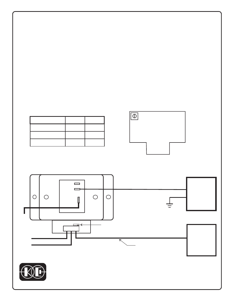
N.O.
COM.
N.C.
1
2
3
March 9, 2004
Figure 1
Figure 2
+12 volts
Ground
TIME DELAY ADJUST
+
Gnd
SIGNAL POLARITY
INPUT SELECTOR
HYDRAULIC
PUMP
CONTROL
HIGH IDLE
SYSTEM
+12 VOLTS WHEN SYSTEM
GOES INTO HIGH IDLE
+12 V
FROM
PUMP
CONTROL
TYPICAL INSTALLATION WITH HIGH IDLE PRECEDING HYDRAULIC PUMP STARTUP
INSTALLATION INSTRUCTIONS
TIME DELAY RELAY - DOPI
DELAY ON PULL-IN
Model 091-100-012
Note: For grounding signal inputs
move signal polarity input
selector switch to the left
Time delay
Adjust
The Model 091-100-012 Time Delay Relay operates in a +12 volt electrical system. The relay
contacts transfer at some time after the application of an input signal to terminal 3. The input
signal may be either +12 volts or a ground as selected by the slide switch adjacent to the
terminal strip. An output relay has contacts capable of switching 30 amperes. A +12 volt
power and ground line are required to operate the time delay circuits. In operation the signal
input to the time delay relay is applied when the first load is energized. At the delay interval
later, the relay closes to operate the second load. The time delay is factory set for either 5 or
60 seconds depending on the model. An adjustment is provided to reduce this or increase it
to the values shown in the table. See figure 1 for time adjustment. Figure 2 illustrates the
Time Delay Relay applied to a High Idle/Hydraulic pump control.
KUSSMAUL ELECTRONICS COMPANY, INC.
631-567-5826,
FAX:
631-567-0314,
TEL:
170 CHERRY AVENUE, WEST SAYVILLE, NEW YORK, 11796-1221 USA
SINCE 1967, DESIGNERS OF INNOVATIVE PRODUCTS
TIME DELAY
Specification
Model A
Model B
Factory Set
5 sec
60 sec
Min Time (CW)
2.4 sec
11 sec
Max Time (CCW)
28 sec
120 sec