Kussmaul Electronics 091-103-012 User Manual
Installation instructions, Time delay relay - dodo, Kussmaul electronics company, inc
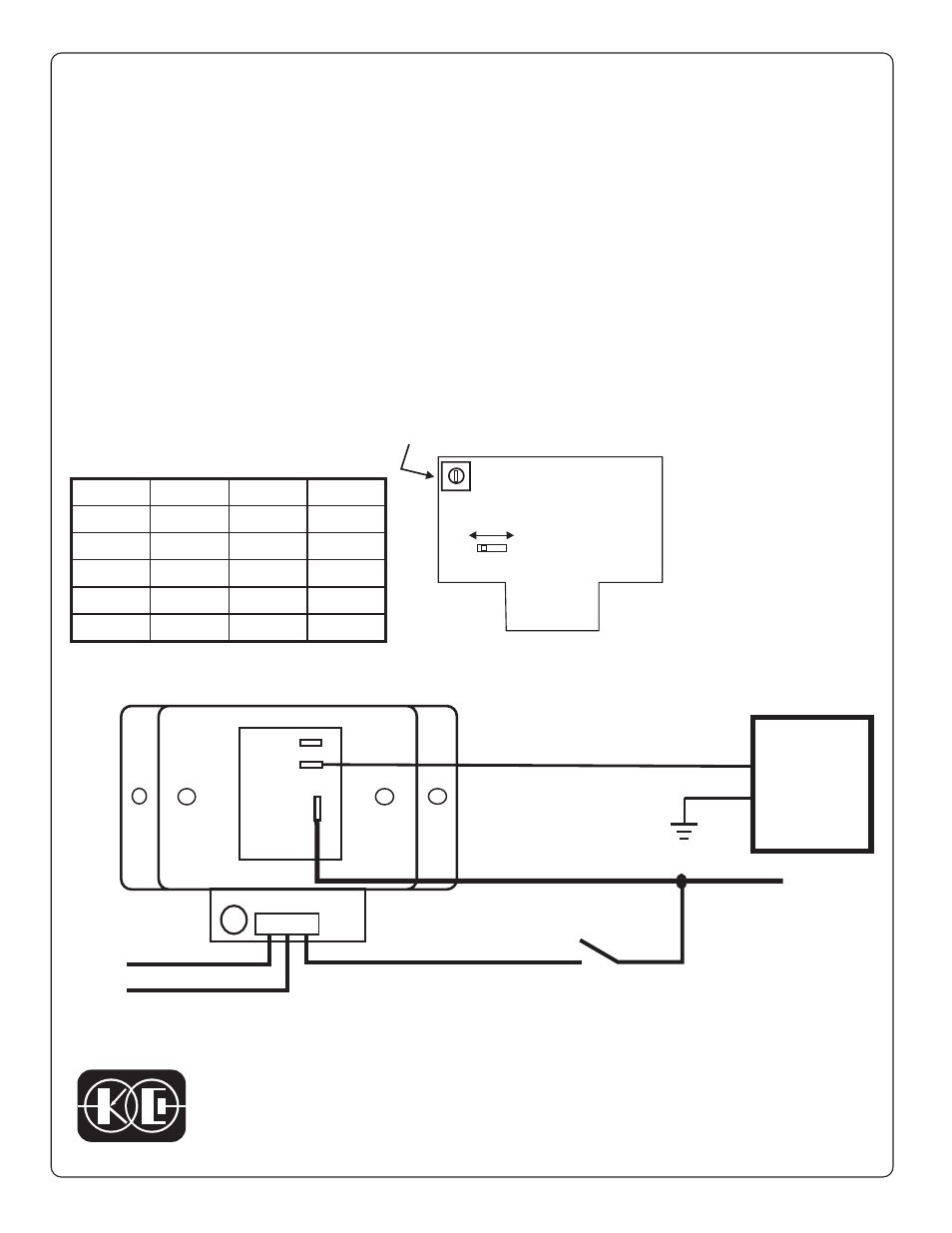
N.O.
COM.
N.C.
1
2
3
JANUARY 9, 2002
Figure 2
+12 volts
Ground
FIGURE1 TIME DELAY ADJUST
Lighting
Circuit
+12 V
FROM
LIGHTING
CIRCUIT
BREAKER
TYPICAL INSTALLATION IN A LIGHTING CONTROL CIRCUIT
INSTALLATION INSTRUCTIONS
TIME DELAY RELAY - DODO
DELAY ON DROP-0UT
Model 091-103-012
RUN
CALIBRATE
Time Delay Adjust
NOTE:
The run/calibrate switch speeds
up the time delay interval by a
factor of 128.
1 second in the calibrate position
is equal to 128 seconds in the
run position
Lighting Control Switch
LIGHTS WILL REMAIN ILLUMINATED FOR THE TIME DELAY
INTERVAL AFTER THE SWITCH IS TURNED OFF
LED illuminates
when relay is
energized
The Model 091-103-012 Time Delay Relay operates in a +12 volt electrical
system. The relay contacts transfer immediately upon the application of an input
signal and remain closed after the signal is removed for the length of the
specified time interval. The range of output times as well as the factory setting is
shown in the table. The output relay contacts are capable of switching 30
amperes.
An adjustment is provided to vary this time at installation. See figure 1. An LED
indicator adjacent to the terminal strip is lit whenever the relay is energized.
Figure 2 illustrates the Time Delay Relay applied to a typical lighting circuit.
Model
Tmin
Tmax
Tset
A
1.25 min
6 min
3 min
B
6 min
27 min
15 min
C
12 min
60 min
30 min
D
4 sec
15 sec
10 sec
E
2 sec
3.3 sec
2 sec
KUSSMAUL ELECTRONICS COMPANY, INC.
631-567-5826,
FAX:
631-567-0314,
TEL:
170 CHERRY AVENUE, WEST SAYVILLE, NEW YORK, 11796-1221 USA
SINCE 1967, DESIGNERS OF INNOVATIVE PRODUCTS