Figure 4 – Kussmaul Electronics 091-158 User Manual
Page 5
Advertising
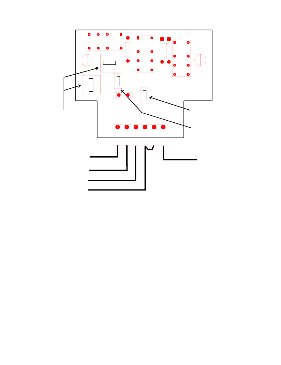
INSTALLATION WIRING FOR USE WITH ONLY 2 INPUT SIGNALS
Input Signal Polarity
AND/OR SELECTORS
Both must be in the
same position
Output Signal Polarity
+12v
+12v
Gnd
Gnd
OR
AN
D
OR
AND
CI1
S3
K1
S2
R3
R2
1
1
1
S4
S1
K3
K2
KUSSMAUL ELECTRONICS INC
091-158-001
1
J1
R1
+12 v
Gnd
Input 1
Input 2
1
2
3
4
5
6
OU
TP
UT
IN
P
U
T
FIGURE 4
OUTPUT
NOTE: All programming switch
positions are identical to 3 input
configuration
Advertising