Kussmaul Electronics 091-178-10A User Manual
Kussmaul electronics company, inc, Wiring diagram, Schematic
KUSSMAUL ELECTRONICS COMPANY, INC.
170 CHERRY AVENUE, WEST SAYVILLE, NEW YORK, 11796-1221 USA
SINCE 1967, DESIGNERS OF INNOVATIVE PRODUCTS
Phone:
Toll Free:
Fax:
E-Mail:
, Web:
(631)567-0314,
800-346-0857,
(631) 567-5826,
www.kussmaul.com
File: 091-178-10A.pmd
Date: July 22, 2009, EAK
INSTALLATION INSTRUCTIONS
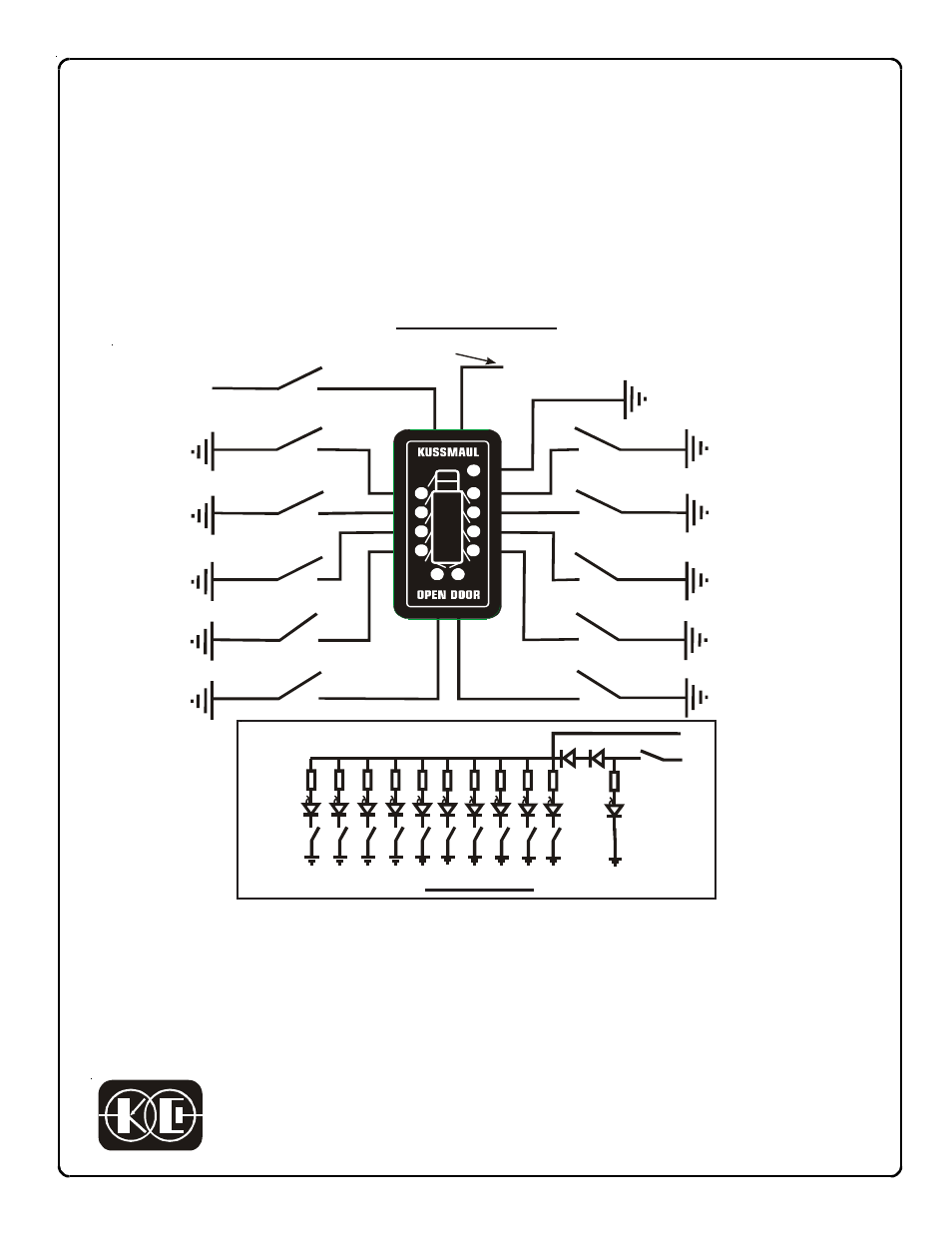
Model 091-178-10A, 10 LED Open Door Display with Alarm Sense
The Model 091-178-10A Open Door Display provides a graphic representation of doors that are
either open or ajar. One LED is wired to a switch at each compartment door. When the compart-
ment or door is opened, the switch provides an electrical path to ground to Illuminate an LED.
Simple and easily installed the display enhances safety and ensures that the operator will not
drive away with an open door. Note that these instructions are for a display with an alarm. For
installations not requiring an alarm use Model 091-178-10.
Wiring Diagram
1. Mount indicator assembly in desired location.
2. Connect the RED wire to +12V through the ignition switch so that the display will be OFF
when the engine is not running. Alternatively, the RED wire may be connected to a constant
12V source to have the display continuously energized.
3. Connect the BLACK wire to GROUND in order to energize the GREEN power indicator.
4. Connect the individual LED’s to the door switches as illustrated in the Wiring Diagram.
Schematic
RED
BLACK
WHITE
GRAY
VIOLET
BLUE
GREEN
YELLOW
ORANGE
Ignition Switch
Door Switch
+12V
WHITE/BLACK
WHITE/GREEN
BROWN
Door Switch
Door Switch
Door Switch
Door Switch
Door Switch
Door Switch
Door Switch
Door Switch
Door Switch
(This wire provides
the ground return
for the power Indicator)
White/Yellow
(Signal output for alarm)
+12v
Ignition
Switch
Door Switches
LED’S
Green
LED
Power Indicator
BLACK WIRE
RED
Signal
White/Yellow