Auto charge 1200, Installation wiring diagram, Connector cable assembly – Kussmaul Electronics 091-53-12-REMOTE User Manual
Page 4
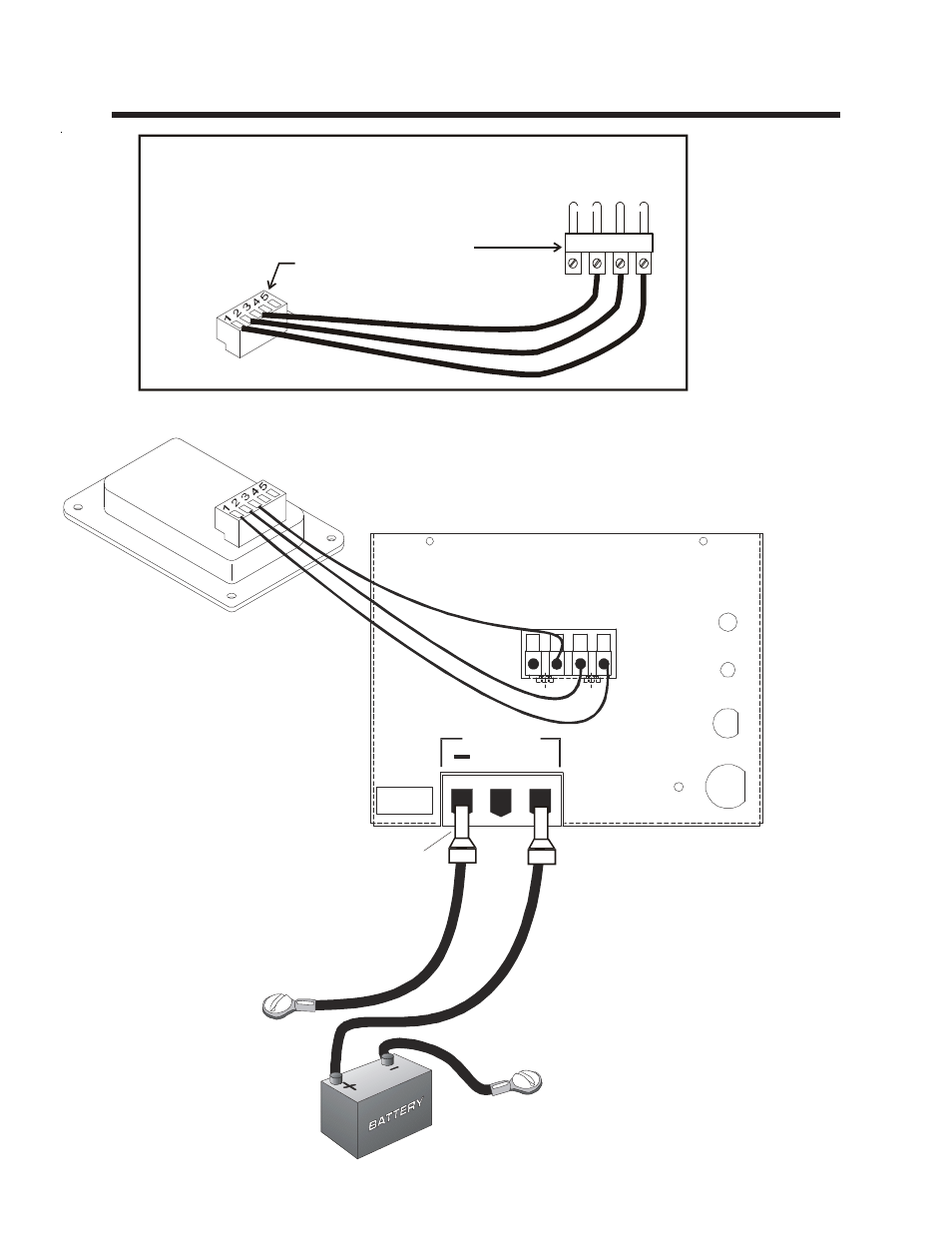
Installation Wiring Diagram
AUTO CHARGE 1200
REMOTE DISPLAY
RED
BLK
WHT
POWER
FUSE
Chassis
Ground
Chassis
Ground
IMPORTANT: WIRE SIZE IS
FOR A LENGTH OF 10 FEET.
IF WIRING IS TO BE LONGER,
6 AWG WIRING IS REQUIRED,
ADDITIONAL INFORMATION IS
AVAILABLE ON REQUEST.
INDICATOR
NOTE INDICATOR WIRING
PIN 1 OF INDICATOR MUST GO TO PIN 1
OF CHARGER, PIN 2 OF INDICATOR MUST
GO TO PIN 2 OF CHARGER AND SO FORTH
PLEASE CHECK CONNECTIONS AND COLOR
OF WIRES BEFORE PLUGGING IN.
USE 8 AWG
or larger on
Output & Gnd
OUTPUT
+
CONNECTOR CABLE ASSEMBLY
Connectors supplied in hardware
pack of indicator
WH
IT
E
BL
AC
K
RE
D
1
2
3
4
NOTE: Minimum wire size on charger
ouput and ground is
Smaller
gauge wire may cause overheating of
terminal. Use 2-966067 wire ferrule
over wireto simplify insertion of wire into
terminal strip and to improve connection.
#8 AWG.
Strip insulation to
11/16” and install
wire ferrule
supplied, 2 places
part# (TERFEB612)