Connections, controls and indicators – LD Systems GT 12 A User Manual
Page 6
6
ENGLISH
DEUTSCH
FRANCAIS
FRANCAIS
FRANCAIS
FRANCAIS
FRANCAIS
ESP
AÑOL
POLSKI
IT
ALIANO
110 -120 V~ / 50 - 60 Hz
120 -240 V~ / 50 - 60 Hz
MAX 300 W / AC~
3
5
6
2
1
4
11
10
8
7
9
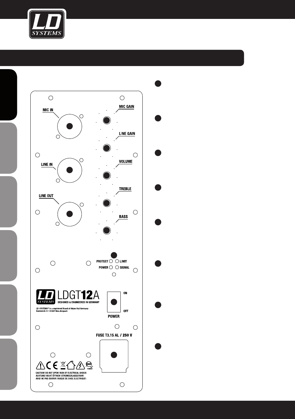
CONNECTIONS,
CONTROLS AND INDICATORS:
1
MIC IN
Balanced microphone input (XLR/ 6.3 mm jack
combo) It is also possible to use an unbalanced
microphone cable (mono jack).
2
MIC GAIN
Volume control for the microphone channel MIC
IN. Turning the knob to the right increases the
volume and turning it to the left decreases it.
3
LINE IN
Balanced line input (XLR / 6.3 mm jack combo) It
is also possible to use an unbalanced line cable
(mono jack).
4
LINE GAIN
Volume control for the line channel LINE IN. Tur-
ning the knob to the right increases the volume
and turning it to the left decreases it.
5
VOLUME
Volume of the sum channel (mix of microphone
channel and line channel). When turned to the
left, levels are lowered, when turned to the right,
they are raised.
6
TREBLE
Equalizer high band for the summing channel.
When turned to the left, levels are lowered, when
turned to the right, they are raised. In the centre
position (resting point), the equalizer is inactive.
7
BASS
Equalizer low band for the summing channel.
When turned to the left, levels are lowered, when
turned to the right, they are raised. In the centre
position (resting point), the equalizer is inactive.
8
LINE OUT
Balanced XLR output for connecting an additional
active speaker or mixer. The input signal consists
of the sum of the channels MIC IN and LINE IN.
LDGT12A shown