Legrand TM8LOCATORI User Manual
Home locator, Localizador para la casa, Instrucciones en español
LIMITED FIVE YEAR WARRANTY
Pass & Seymour/Legrand will remedy any defect in workmanship or material in Pass & Seymour/Legrand
products which may develop under proper and normal use within five years from the date of purchase by a
consumer:
(1) by repair or replacement, or, at Pass & Seymour/Legrand’s option, (2) by return of an amount equal to the
consumer’s purchase price. Such remedy is IN LIEU OF ANY AND ALL EXPRESSED OR IMPLIED
WARRANTIES OF MERCHANTABILITY OR FITNESS FOR A PARTICULAR PURPOSE. Such remedy by
Pass & Seymour/Legrand does not include or cover cost of labor for removal or reinstallation of the product.
ALL OTHER FURTHER ELEMENTS OF DAMAGE (INCIDENTAL OR CONSEQUENTIAL DAMAGES) FOR
BREACH OF ANY AND ALL EXPRESSED OR IMPLIED WARRANTIES INCLUDING WARRANTIES OF
MERCHANTABILITY OR FITNESS FOR A PARTICULAR PURPOSE ARE EXCLUDED HEREBY. (Some
states do not allow disclaimer or exclusion or limitation of incidental or consequential damages, so the
above disclaimers and limitation or exclusion may not apply to you.) ANY IMPLIED WARRANTIES
INCLUDING WHERE REQUIRED WARRANTIES OF MERCHANTABILITY OR FITNESS FOR A PARTICULAR
PURPOSE SHALL BE LIMITED TO THE FIVE YEAR PERIOD SET FORTH ABOVE. (Some states do not
allow limitation on how long an implied warranty lasts, so the above limitation may not apply to you.)
To ensure safety, all repairs to Pass & Seymour/Legrand products must be made by Pass &
Seymour/Legrand or under its specific direction. Procedure to obtain performance of any warranty
obligation is as follows: (1) Contact Pass & Seymour/Legrand, P.O. Box 4822, Syracuse, NY 13221 for
instructions concerning return or repair; (2) return the product to Pass & Seymour/Legrand, postage paid,
with your name and address and a written description of the installation or use of the Pass &
Seymour/Legrand product, and the observed defects or failure to operate, or other claimed basis for
dissatisfaction.
This warranty gives you specific legal rights and you may also have other rights which vary from state to state.
WIRING AND INSTALLATION DIAGRAMS BELOW
To be installed by a certified electrician or other qualified person.
WARNING – To prevent severe shock or electrocution, always turn power OFF
at the service panel before installing this unit, working on the circuit,
or changing a lamp.
CAUTION – For permanently installed incandescent lights only. To reduce the
risk of overheating and possible damage to other equipment, do not install the
Home Locator to control a receptacle, a fluorescent light or compact fluorescent
light bulb, a motor-operated appliance, a transformer supplied appliance, photo-
cell or motion detector based lighting.
Do not use the Home Locator with incandescent lamps whose power require-
ment exceeds maximum power (stated in watts) of the Home Locator.
Do not connect the Home Locator to a power source other than 120VAC, 60Hz only.
A 25W minimum power load is required.
DIRECTIONS:
1. Disconnect power to the circuit by removing the fuse or turn the circuit
breakers OFF before installing.
2. Remove the wall plate and switch mounting screws, pull the existing switch
from the wall box.
NOTE: Prior to installation, the Air Gap switch should be in the OFF position
(Down), to disconnect the switch circuit from the power source (see Locator
Functions).
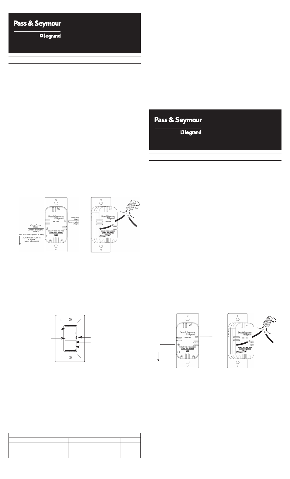
3. Connect the Home Locator as shown in the installation and wiring diagrams,
using the enclosed wire nuts. Device uses 18 gauge wire (see Table 1 for wire
ranges). Install the Home Locator in the wall box, with the word “TOP” on the
metal strap right side up, using the mounting screws provided.
4. Replace the wall plate; restore the power connection to switch. Then slide the
Air Gap switch to the ON position (Up). The green indicator should glow.
OPERATION INSTRUCTIONS: (refer to Locator Functions)
1. Press the top of the paddle to turn exterior house light on. Press the bottom
of the paddle to turn exterior house light off.
(Red indicator glows when the exterior house light is ON, green indicator glows
when the exterior house light is OFF.)
2. Press the button to activate the home locate mode (light flashes per S.O.S.
code); press again to turn off. (Red indicator also flashes with S.O.S. code.)
NOTE: In an emergency, first call your local emergency services hotline (in many
areas 911) and give them all requested information including your home address.
Instruct them to look for the flashing exterior house light.
CAUTION:
1. Always slide the Air Gap switch in the full down (OFF) position when changing
a light bulb.
2. Either LED illumination indicates a working exterior house light. Should the
LED illumination be absent, check the light bulb. It may be burned out or loose
in the socket.
NOTE: For optimum use as an emergency lighting device, the home locator
should be used on an outside house or porch light, easily visible from your street.
Use only copper or copper clad wire with this device.
This device complies with Part 15 of the FCC Rules. Operation is subject to the
following two conditions: (1) This device may not cause harmful interference, and
(2) this device must accept any interference received, including interference that
may cause undesired operation.
This Class B digital apparatus complies with Canadian ICES-003.
Table 1
R E A D
A N D
S A V E
T H E S E
I N S T R U C T I O N S !
INSTRUCCIONES EN ESPAÑOL
L E A Y
G U A R D E
E S T A S
I N S T R U C C I O N E S
Installation Diagram
Wiring Diagram
Locator Functions
AIR GAP SWITCH
LED ILLUMINATION
PRESS HERE FOR
HOME LOCATE FUNCTION
HOME
LOCATOR
Single Pole
500 Watt
120VAC
60Hz
LOCALIZADOR
PARA LA CASA
Unipolar
500 Watts
120 VCA
60 Hz
PRESS HERE
TO TURN ON
PRESS HERE
TO TURN OFF
WIRE CONNECTOR USAGE CHART
WIRE COMBINATIONS
STRIP LENGTHS
COLOR
1#14 & 1#16; 1#14 & 2#18; 2, 3#16;
#14 – 1/2", #16 & #18 – 9/16"
ORANGE
1#16 & 1 – 3#18; 3 – 5#18; 2#18
1#14 & 1, 2#16; 1#14 & 1, 2#18;
#14 & #16 – 7/16", #18 – 1/2"
IVORY
2, 3#16; 2 – 5#18
LOS DIAGRAMAS DE CABLEADO E INSTALACIÓN SE PRESENTAN ABAJO
Para ser instalado por un electricista certificado o persona competente.
ADVERTENCIA – Para evitar serios electrochoques o electrocución, siempre
apague el suministro eléctrico en el panel de servicio antes de instalar esta
unidad, trabajar en el circuito o cambiar una bombilla.
PRECAUCIÓN – Para luces incandescentes instaladas de manera permanente
únicamente. Para reducir el riesgo de recalentamiento y los posibles daños a
otros equipos, no instale el Localizador para la casa para controlar un
receptáculo, una luz o tubo fluorescente, un electrodoméstico a motor, un
electrodoméstico equipado con transformador, una luz controlada por célula
fotoeléctrica o por detector de movimiento.
No use el Localizador para la casa con lámparas incandescentes cuyo consumo
máximo exceda la potencia máxima (indicada en watts) del Localizador para la
casa.
Conecte el Localizador para la casa únicamente a una fuente eléctrica de 120
VCA, 60 Hz.
Requiere una carga mínima de 25 W.
INSTRUCCIONES:
1. Antes de instalar, desconecte el suministro eléctrico al circuito, quite el fusible
o apague los disyuntores (OFF).
2. Retire la placa de pared y los tornillos de montaje del interruptor y retire el
interruptor existente de la caja de pared.
NOTA: Antes de proceder con la instalación, el microinterruptor debe estar
apagado (en la posición OFF, hacia abajo). Para desconectar el circuito del
interruptor, consulte Funciones del Localizador.
3. Conecte el Localizador para la casa con los capuchones para alambres
suministrados, tal como se muestra en los diagramas de cableado e
instalación. El dispositivo utiliza alambres calibre 18 (consulte la Tabla 1 para
determinar el calibre de los alambres). Instale el Localizador para la casa en la
caja de pared con los tornillos de montaje suministrados y con la palabra
“TOP” impresa en la banda metálica hacia arriba.
4. Vuelva a colocar la placa de pared y restaure el suministro eléctrico al
interruptor. Deslice el microinterruptor a la posición ON (encendido, arriba). El
indicador verde se ilumina.
INSTRUCCIONES DE OPERACIÓN: (Consulte Funciones del Localizador.)
1. Presione la parte superior de la paleta para encender la luz exterior de la casa.
Presione la parte inferior de la paleta para apagar la luz exterior de la casa.
(El indicador rojo se ilumina cuando la luz exterior de la casa está encendida. El
indicador verde se ilumina cuando la luz exterior de la casa está apagada.)
2. Presione el botón para activar la modalidad de localización para la casa (la luz
destella “S.O.S.” en código Morse). Oprima nuevamente para apagarla. (El
indicador rojo también destella “S.O.S.” en código Morse.)
NOTA: En una emergencia, llame primero a la línea telefónica directa de servicios
de emergencia local (911 en muchas áreas) y proporcione toda la información
solicitada, incluso la dirección de su casa. Indique que deben buscar la casa
cuya luz exterior destella intermitentemente.
PRECAUCIÓN:
1. Siempre deslice el microinterruptor completamente hacia abajo (OFF,
apagado) cuando cambie una bombilla.
2. Tanto una como otra iluminación de LED indica que la luz exterior funciona.
En caso de estar apagada, inspeccione la bombilla que puede estar floja o
quemada.
Alambre a la fuente
(Negro)
Alambre
a la lámpara
(Negro)
ALAMBRE DE
PUESTA A TIERRA
(Verde o Desnudo)
Girar
Diagrama de instalación
Diagrama de cableado