Legrand LSLV600BK User Manual
Trademaster, Magnetic low voltage dimmers
INSTALLATION INSTRUCTIONS
TradeMaster
®
MAGNETIC LOW VOLTAGE DIMMERS
R E A D A N D S A V E T H E S E I N S T R U C T I O N S !
To be installed by a certified electrician or other qualified person.
WARNING – To prevent severe shock or electrocution, always turn power
OFF at the service panel before installing this unit, working on the circuit, or
changing a lamp.
Caution – To reduce the risk of overheating and possible damage to other
equipment, do not install to control a receptacle, or a motor-operated
appliance. Connect dimmers only in a 120VAC, 60 Hz circuit to control the
primary of a transformer-supplied incandescent load. Maximum VA rating of
dimmer applies to transformer input, not load on the transformer secondary.
Do not use dimmer with incandescent lamps whose power requirements
exceeds maximum power (stated in Watts) of the dimmer.
Do not use to control a solid-state electronic low-voltage transformer.
Use copper wire only.
DIRECTIONS
1. Disconnect power to circuit at the panel by removing fuse or turn circuit
breakers OFF before installing.
2. Remove wall plate and switch mounting screws, pull existing switch from
wall box.
3. Disconnect existing switch from circuit. 3-Way Installation: Identify the
“COMMON” wire (wire connected to the terminal marked common or odd
colored terminal). For “new” installation identify wire connected to power
source or to the load.
4. Connect dimmer as shown in the installation diagram using #12 or #14
AWG stranded or solid copper conductors. Strip wire using gauge on back
of device.
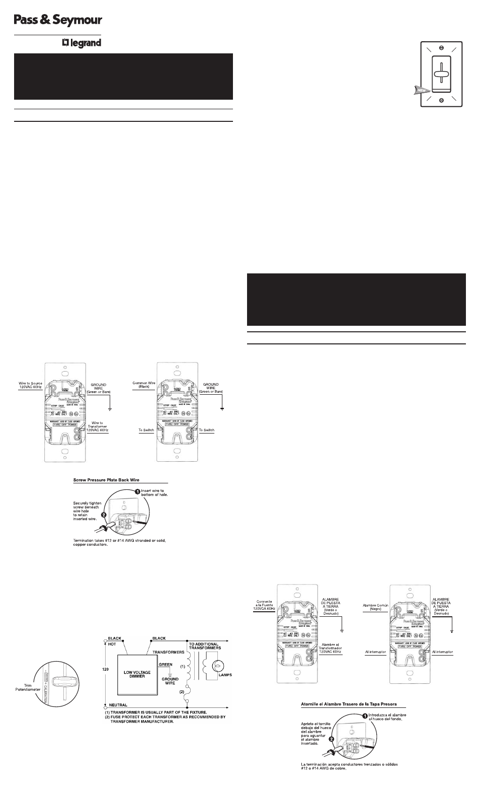
INSTALLATION DIAGRAM
5. Install dimmer in wall box, with word ‘TOP’ on the strap right side up, using
mounting screws provided.
6. Attach wall plate and restore power to circuit.
7. Dimmer may need to be adjusted to accommodate low voltage transformer.
To do this, DISCONNECT POWER FROM CIRCUIT, and remove the wall
plate. Use a small insulated, flat tipped screwdriver to adjust the trim pot,
which is accessible via the slot (marked CALIBRATION) provided on the
strap. Turn down to increase the minimum light intensity setting. Next,
mount the wall plate back, restore the power, and test. Repeat above as
necessary. Note: Never adjust the trim pot when circuit is live.
8. Remove protective film after the wall plate is installed.
Note: Even with this protective film, sheet rock, dust and paint can enter
and damage this device. This device should be installed after sheet rocking
and painting are completed.
Single Pole
3-Way
NOTE: It is normal for the dimmer to feel warm during operation. A 25W
minimum load is required. Use a separate neutral wire for each phase of a
multiphase system containing a dimmer, and for high power single phase
applications where flickering is present.
LIGHT MODULE:
(Sold separately, Catalog #TM8LMCC)
Transform in minutes a standard dimmer into an
illuminated dimmer (ON when light is OFF) – allows
the dimmer to be found in the dark.
Average 20-year life expectancy.
No wiring – quick snap-in installation.
WARRANTIES
Lifetime Warranty. The device you have purchased is warranted under normal use against
defects in workmanship and materials for as long as you own the device. If the device fails
due to manufacturing defect during normal use, return the device for replacement to the
store where purchased or send to:
Pass & Seymour Legrand
50 Boyd Avenue
Syracuse, NY 13209
All requests for replacement must include a dated sales receipt (legible copies accept-
able).
ALL OTHER WARRANTIES, INCLUDING BUT NOT LIMITED TO ANY WARRANTIES OF
MERCHANTABILITY OR FITNESS FOR A PARTICULAR PURPOSE, ARE LIMITED TO A
PERIOD OF TWO YEARS FROM THE DATE OF PURCHASE. YOUR SOLE AND EXCLU-
SIVE REMEDY AGAINST PASS & SEYMOUR LEGRAND UNDER ANY WARRANTY SHALL
BE THE EQUIVALENT REPLACEMENT OF THE DEVICE. IN NO EVENT SHALL ANY WAR-
RANTY APPLY TO ANY DEFECT ARISING OUT OF ANY ALTERATION OF THE DEVICE,
IMPROPER WIRING, IMPROPER INSTALLATION, MISUSE, ABNORMAL USE OR NEGLI-
GENCE. IN NO EVENT SHALL PASS & SEYMOUR LEGRAND BE LIABLE FOR LOST
PROFITS, INDIRECT, SPECIAL, EXEMPLARY, INCIDENTAL OR CONSEQUENTIAL DAM-
AGES. Some states do not allow limitations on how long implied warranties last and do
not allow exclusion or limitation of incidental or consequential damages. Some of the
above limitations or exclusions may not apply to every purchaser.
Para ser instalado por electricista certificado u otra persona capacitada.
ADVERTENCIA: Para prevenir una sacudida eléctrica severa o
electrocución, siempre CORTE la electricidad en el panel de servicio antes
de instalar esta unidad, trabajar en el circuito, o cambiar una lámpara.
AVISO: Para reducir el riesgo de recalentamiento y posiblemente dañar a
otro equipo, no instale para controlar un receptáculo, un artefacto
motorizado. Conecte el reductor de luz solo en circuito de 120VAC, 60Hz
para controlar el primario de una carga incandescente alimentada por
transformador.
Máxima potencia de VA del reductor de luz se aplica a la entrada del
transformador, no a la carga sobre el secundario del transformador.
No use el reductor de luz con lámparas incandescentes cuyas requisitos de
potencia exija la potencia máxima (indicada en Wats) del reductor de luz.
No usar para controlar un transformador electrónico de baja tensión.
Solo utilice cables de cobre.
INSTRUCCIONES:
1. Corte la electricidad al circuito en el panel quitando el fusible o APAGANDO
el interruptor automático antes de la instalación.
2. Quite la chapa de pared y los tornillos de montura de chucho, hale el
chucho existente de la caja embutida en la pared.
3. Desconecte el interruptor existente del circuito. Instalación 3-Vías:
Identifique el alambre “COMUN” (alambre conectada a la terminal marcada
común o alambre de color diferente). Para instalaciones “Nuevas”
identifique los alambres conectados a la fuente eléctrica o a la carga.
4. Conecte el reductor de luz como mostrado en el diagrama de instalación
utilizando alambre trenzado o sólido #12 o #14 AWG de cobre. Pele el
alambre utilizando la guÌa en la parte trasera del aparato.
DIAGRAMA DE INSTALACIÓN
Posta Solo
De Tres Direcciones
INSTRUCCIONES DE INSTALACIÓN
TradeMaster
®
ATENUADORES MAGNÉTICOS
DE BAJA TENSIÓN
INSTRUCCIONES EN ESPAÑOL
L E A Y G U A R D E E S T A S I N S T R U C C I O N E S
Wiring Diagram