Legrand 92080GRY User Manual
Incandescent dimmers, Installation instructions
To be installed by a certified electrician or other qualified person.
WARNING – To prevent severe shock or electrocution, always turn power
OFF at the service panel before installing this unit, working on the circuit, or
changing a lamp.
CAUTION – To reduce the risk of overheating and possible damage to other
equipment, do not install incandescent dimmer to control a receptacle, a
fluorescent light, a motor-operated appliance, or a transformer-supplied
appliance.
Do not use dimmer with incandescent lamps whose power requirements
exceeds maximum power (stated in Watts) of the dimmer.
Do not connect dimmer to power source other than 120VAC, 60 Hz only.
Use copper wire only.
DIRECTIONS
1. Disconnect power to circuit by removing fuse or turn circuit breakers OFF
before installing.
2. Remove wall plate and switch mounting screws, pull existing switch from
wall box.
3. Disconnect existing switch from circuit.
3-way installation: Identify the
“COMMON” wire (wire connected to the terminal marked common or odd
colored terminal). For “new” installation identify wire connected to power
source or to the load.
4. Connect dimmer as shown in the installation diagram with wire connectors
provided.
5. Install dimmer in wall box, with words on the dimmer right side up, using
mounting screws provided.
6. Attach wall plate, then restore power to the circuit.
NOTE: It is normal for the dimmer to feel warm during operation. A 50W
minimum load is required. Use a separate neutral wire for each phase of a
multiphase system containing a dimmer, and for high power single phase
applications where flickering is present.
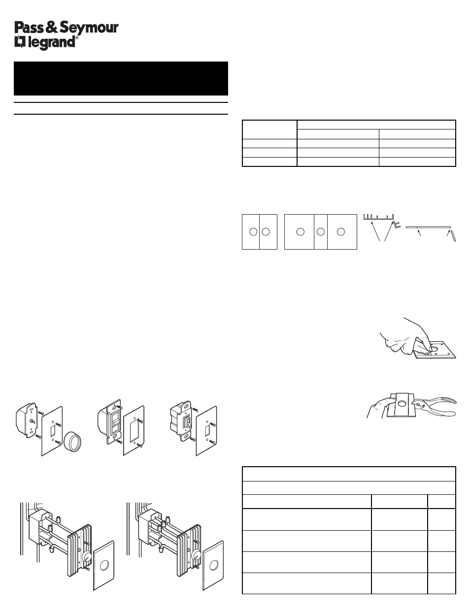
DIMMER TYPES
INSTALLATION DIAGRAM (wiring is same with each of dimmer types)
MULTIPLE GANGING OF DIMMERS
Any combination of dimmer models may be ganged together. Using vise or
heavy-duty pliers, remove the outer fins on either or both sides, as necessary,
at the break-off points on the thin metal line at the base of the third fin.
Dimmers can be ganged without removing fins by proper selection and
placement of outlet boxes. When fins are removed, de-rate the maximum load
according to the following De-Rating Table:
MAXIMUM
FINS REMOVED
LOAD
ONE SIDE
TWO SIDES
1000W
800W
700W
1500W
1400W
1300W
2000W
1800W
1600W
CAUTION : Sharp or jagged metal edges might be exposed where sections
were broken off. Use care when handling the dimmer after this operation.
ILLUSTRATION FOR GANGING
HOW TO CUT PLASTIC FACEPLATE:
If fins are removed for ganging, the faceplate must be adjusted to match.
You may either score the groove on the back of the faceplate thoroughly with
a razor sharp packing knife, or you may partially score the groove, then
complete the break with pliers.
TO CUT THE FACEPLATE WITH KNIFE ONLY:
1. Lay faceplate face down on soft clean cloth,
on a flat solid surface to preserve finish.
2. Run knife vertically throughout groove
repeatedly until plastic separates.
3. Dress rough edges using very fine-grained
sand paper.
TO CUT THE FACEPLATE USING PLIERS AND KNIFE:
1. Lay faceplate face down on soft clean
cloth, on a flat solid surface to preserve
finish.
2. Run knife vertically throughout groove
several times.
3. Hold faceplate firmly in one hand and use
pliers to bend the flat edge of the fin away from the groove. Behind the
opposing ends first, then make a final break at the middle, separating fin
from faceplate.
4. Dress rough edges using very fine-grained sand paper.
INSTALLATION INSTRUCTIONS
INCANDESCENT DIMMERS
R E A D A N D S A V E T H E S E I N S T R U C T I O N S !
Double-Gang
Rotary
Slide
Toggle
Mixed Combination-Gang
Fin Break-Off Points
WIRE NUT USAGE CHART
Use Only Copper Wire With This Device
Wire Combinations
Strips Lengths
Color
1#14 & 1#16; 1#14 & 2#18; 2,3#16; 1#16 & 1-3#18;
1/2" Except 9/16"
Orange
3-5#18; 2#18
For #16 & #18 AWG
1#10 & 1#14; 1#12 & 1#14 2,3#14; 2#14 &1,2#16;
1/2" Except 5/8"
Yellow
2#14 & 2,3#18;1#14 & 1-4#16; 1#14 & 1-4#18
For #18 AWG
1#10 & 1,2#12; 1#10 & 1-3#14; 2,3#12; 1#12 &
7/16" Except 1/2"
Red
1-3#14; 1#12 & 3#16; 3,4#14
For #16
1#14 & 1,2#16; 1#14 & 1,2#18; 2,3#16; 2-5#18
7/16" For #14 & #16
Ivory
1/2" For #18
GREEN
T
O
GROUND
BLACK
NEUTRAL
WHITE
BLACK
TO 120V SOURCE
TO LAMPS
GREEN
T
O
GROUND
RED
BLACK OR
YELLO
W
TO 3 WAY SWITCH
NEUTRAL
WHITE
BLACK
COMMON
Single Pole
Three Way