Legrand EDF V-Trough User Manual
V-trough, Installation guidelines, Planning
V-Trough
INSTAllATION GUIDElINES
data cable fill table
Mc Power cable fill table
MAX NUMBER OF CABLES PER CODE
MAX NUMBER OF CABLES PER CODE
TRAY
Cat 5e 4-pr
Plenum (.17”)
Cat 5e 4-pr
Non-Plenum (.19”)
Cat 6e 4-pr
Plenum (.22”)
Cat 6a 4-pr
Plenum (.35”)
2C (12 AWG) THHN
TypeMC AlumArmor
3C (12 AWG) THHN
TypeMC AlumArmor
VT 50/50 (2x2)
88
71
53
20
11
10
VT 50/100 (2x4)
177
142
106
41
23
21
VT 50/200 (2x8)
355
284
212
83
47
42
VT 50/300 (2x12)
532
426
318
125
71
63
VT 100/100 (4x4)
351
281
209
82
23
21
VT 100/200 (4x8)
703
563
419
165
47
42
VT 100/300 (4x12)
1055
844
629
248
71
63
VT 100/500 (4x20)
1758
1407
1049
414
119
105
VT 100/600 (4x24)
2110
1689
1259
497
143
126
Planning
Use these cable fill tables to determine the tray size(s) needed for your installation.
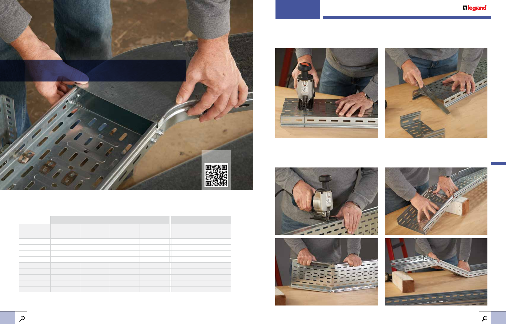
Cutting straight seCtions
v-Trough can be cut to length with a reciprocating saw fitted with a fine metal cutting blade. Mark three sides of
the tray using a square and make allowances to keep mounting hole slots in position for splicing to other straight
sections or fittings. use a flat file to remove all rough edges. Cover sections can be modified in the same way.
Cutting straight seCtions for elevation Changes
Cut only the sides of the tray for changes in cable pathway elevations. Make a 90 degree cut in both sides of
the tray for a downward bend. for an upward bend, make a double cut to form a notch. The notch should be
sized to fit the tray angle needed. Then, using a straight edge, form the tray to the proper angles.
View V-Trough
Installation Video
www.LEGRAND.us/cAbLofiL
19
For detailed dimensions, see pages 22-23. For finish descriptions, see page 25.
www.LEGRAND.us/cAbLofiL
18
iN
sT
ALLA
Tio
N
s
iN
sT
ALLA
Tio
N
s
v-TRouGh
iNsTALLATioNs