Legrand 861 Series Outlet Boxes for Wood User Manual
861 series outlet boxes for wood & raised floors
861 Series Outlet Boxes
for Wood & Raised Floors
I N S T A L L A T I O N I N S T R U C T I O N S
Installation Instruction No.: 1 002 968R1 – Updated November 2005
Walker
®
electrical systems conform to and should be properly
grounded in compliance with requirements of the current National
Electrical Code or codes administered by local authorities.
All electrical products may present a possible shock or fire
hazard if improperly installed or used. Walker electrical products
may bear the mark as UL Listed and/or Classified and should
be installed in conformance with current local and/or the
National Electrical Code.
IMPORTANT: Please read all instructions
before beginning.
Products Covered: 861, 861QTC, 861AMDTC, 861AMDRTTC, & 861FFTC
Applications:
This unit is for wood floor and raised floor construction with:
• 3/4" [19.1mm] subflooring with carpet and padding or
• 3/4 [19.1mm] subflooring with 1/4" underlayment and tile or linoleum floor covering.
These requirements represent the minimum floor thickness to ensure enough cross section is available for the box to lock
into the subflooring.
• Suitable for use in air handling spaces in accordance with sec. 300-22(C) of the National Electrical Code.
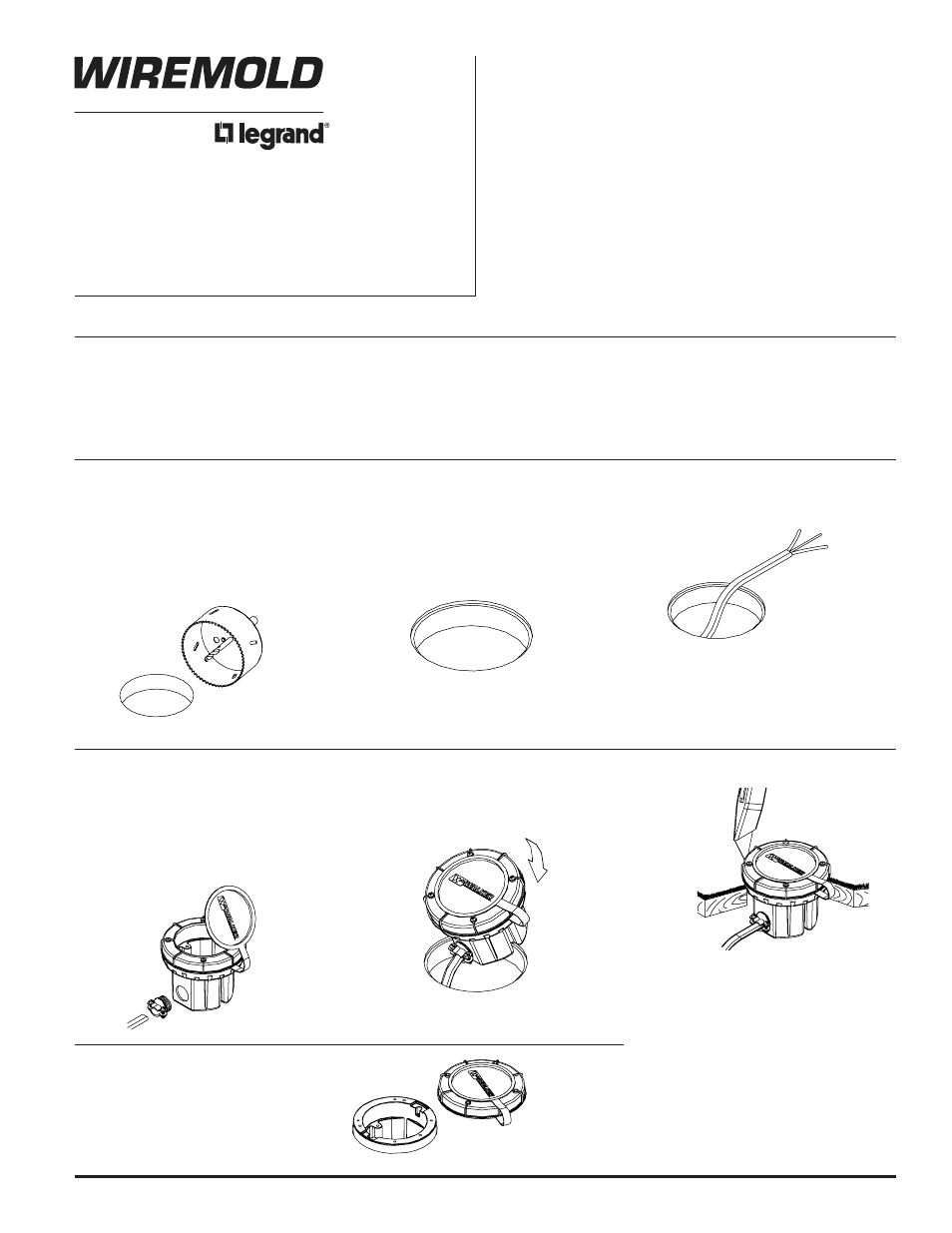
BOX INSTALLATION
1. Determine the floor box location.
(Make sure the placement does not
interfere with obstructions below
such as floor joists, HVAC duct, light
fixtures, etc.) Drill a hole through
the flooring using a 4" [102mm] hole
saw (4 1/16" [104mm] actual).
2. For a flush installation in hardwood or
tile floors with the 895T or 896T series
covers - cut a 4 5/16" [109mm] diam-
eter, 1/8" [3.2mm] deep step in
the final floor covering.
3. Pull the nonmetallic sheathed cable or
armor clad cable up to and through
the 4" [102mm] hole.
NOTE: For air handling spaces allowed for that
application. See NEC 300-22(C). For
communications applications, type CMP
communication plenum cable is required
in raised floor plenums when wiring
methods as described in NEC article
300-22(C) are not followed.
4. Remove the appropriate 1/2" [12.7mm]
trade size knockout and attach a cable
connector to accommodate the wiring
system being used.
Attach the wiring system to the box.
To access the wiring cavity, open the
disposable cover cap and reseal after
use to avoid debris entry.
5. Orient the box to the desired rotation
and push into the hole. The box will
not turn once installed so make sure
the receptacle will be parallel or
perpendicular with any adjacent walls.
6. Use the disposable cover as a template
to trim around when installing carpet
or tile.
NOTE: Refer to carpet/tile cutout
template when installing the
following catalog numbers:
861QTC, 861CMDTC,
861CMDRTTC, 861FFTC.
7. When wiring the final activation, remove
the disposable cover taking care not to
push the box through the opening.