Legrand SGT-ACT User Manual
Raised floor box, Cat. nos. af1 and af2, Installation instructions
1. Prior to installing the Walker Raised Floor Box, an 8" x 6" [203mm
x 152mm] (+1/16" - 0") opening must be cut or formed in the raised
floor panel.
2. Carpet squares need to be laid in position if not pre-attached to
the panel, and an 8" x 6" [203mm x 152mm] opening needs to be
cut over the opening in the panel prior to pulling wires and cables
to the box.
3. The Walker Raised Floor Box will accept up to four power devices
or a combination of power and low voltage devices in its three
compartments. The power and low voltage configurations must
be determined.
Caution: Do not mix power and low voltage devices in the
same compartment.
4. Due to the unique structure of the box, all wires and cables can be
attached prior to attaching the unit to the raised floor panel and
while the floor is in place. Wire and cables are pulled under the
floor and brought out through the mounting hole.
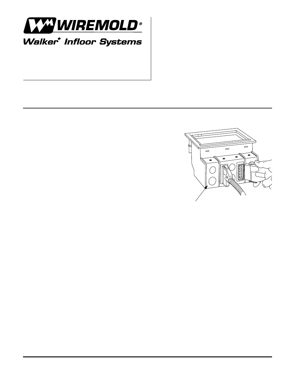
5. Low voltage cables may be pulled through a bushing in one of the device plates, or may be attached to a device
that is mounted to the box or a device plate. The back cover must be attached behind a compartment used for low voltage
except in installations where the raised floor is not used as a plenum. Where required by local codes, connect conduit to the
back cover. Type CMP communications plenum cable is required in raised floor plenums when wiring methods as described
in NEC Article 300.22 are not followed.
6. a. Field Wired Boxes – Cat. No. AF1:
The power compartments of these boxes are to be field wired. Use only UL Listed receptacles. Feed enough flexible
conduit to the hole in the panel to extend at least 18" [457mm] above the raised floor panel. Attach a conduit connector to
the conduit. Remove the appropriate knockout from the back cover and attach the conduit connector. At least 9" [229mm]
of wire should extend beyond the conduit connector. Wire the devices in accordance with the National Electrical Code and
attach the back cover to the box. Mount devices to the box and install device cover plates.
b. Prewired Boxes – Cat. No. AF2:
The boxes are prewired with Walkerflex
®
Prefabricated Modular Wiring System. Follow the installation instructions
supplied with the Walkerflex System to connect the power cables to the box.
Raised Floor Box
Cat. Nos. AF1 and AF2
INSTALLATION INSTRUCTIONS
Installation Instruction No.: IJ0100 R1 – Updated April 2003
Walker
®
electrical systems conform to and should be properly
grounded in compliance with requirements of the current National
Electrical Code or codes administered by local authorities.
All electrical products may present a possible shock or fire
hazard if improperly installed or used. Walker electrical products
may bear the mark as UL Listed and/or Classified and should
be installed in conformance with current local and/or the National
Electrical Code.
IMPORTANT: Please read all instructions
before beginning.
NOTE: Products are suitable for use in air handling spaces in accordance with
Sec. 300-22(C) of the National Electrical Code.
Back Cover Shown