Legrand 862 User Manual
862 series outlet boxes for wood & concrete floors
862 Series Outlet Boxes
for Wood & Concrete Floors
I N S T A L L A T I O N I N S T R U C T I O N S
Installation Instruction No.: 43367R2 – Updated August 2006
Wiremold / Legrand and Pass & Seymour / Legrand
electrical systems conform to and should be properly
grounded in compliance with requirements of the
current National Electrical Code or codes
administered by local authorities.
All electrical products may present a possible shock
or fire hazard if improperly installed or used. Wiremold
/ Legrand and Pass & Seymour / Legrand electrical
products may bear the mark as UL Listed and/or
Classified and should be installed in conformance
with current local and/or the National Electrical Code.
IMPORTANT: Please read all instructions
before beginning.
Products Covered:
Floor Box Only: 862
Floor Box & Cover: 862CK-1/2, 862TCK-1/2, 862CKAL-1/2, 862TCKAL-1/2
Floor Box, Cover & Receptacle: 862DB, 862C, 862GFI, 862TGFI, 862SP, 862TSP, 862TCAL, 862TAL,
862GFICAL, 862TGFIAL, 862SPCAL, 862TSPAL
APPLICATIONS:
862 Series Floor Boxes can be installed in either a wood floor or a concrete floor on-grade application. When
mounting wire to the 862 Series Floor Box, use the appropriate 3/4" trade size cable connector. When mounting
rigid plastic conduit to the 862 Series Floor Box, use a male PVC conduit fitting adapter.
NOTES:
• Wire cable connectors and conduit fitting adapters are not included.
• Purchase kit (862KIT) when installing in a concrete floor. Kit includes a mud cap, gasket, and two 3/4" trade
size male PVC conduit fitting adapters.
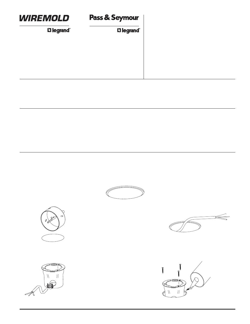
1. Determine the floor box location. (Make
sure the placement does not interfere with
obstructions below such as floor joists, HVAC
duct, light fixtures, etc.) For a flush installation
in hardwood or tile floors when using the tile
version covers – cut a 4 1/2" [114mm]
diameter, (See Table 1 – Depth of Cut “A”)
deep step in the finished floor covering. DO
NOT CUT THROUGH THE FLOOR. (See
Alternate method of cutting Step #4)
2. Using the pilot hole from step 1 drill a 3 3/4"
[92mm] hole through the floor. Carefully
remove the material on the depth of cut
ledge by chipping it away with a chisel or
flat screwdriver blade.
3. When mounting on carpet, cut a 4 1/2"
[114mm] diameter, (See Table 2 – Depth of
Cut “B”) deep step in the sub-floor to leave a
1/8" [3.2 mm] gap to sandwich the carpet
between the cover and the floor. If your
carpet is thicker or thinner than 1/8” [3.2 mm],
adjust the numbers in Table 2 accordingly.
Remove the material on the depth of cut step
by chipping it away with a chisel or flat
screwdriver blade.
5. Pull the nonmetallic sheathed cable or
armor-clad cable up through the hole.
6. Remove the appropriate 3/4" trade size
knockout and attach a cable connector to
the box. Attach the wiring system to the box.
4. Alternate method of cutting 3/8" [10 mm] step
in wood floor. Drill a hole through the wood
flooring using a 3 3/4" [92mm] hole saw.
Determine the depth of cut needed for your
application using Table 1 or Table 2. Set the
router to the correct depth of cut and use a
rabbeting bit with a 3/8" [10 mm] rabbet to
route the step into the wood floor.
7. Orient the box to the desired rotation and
push it into the hole. Adjust the box to make
sure the receptacle will be parallel or
perpendicular to any adjacent walls. Use
three #6 x 3/4" wood screws provided to
attach the box to the floor. Caulking or
grouting around the metal ring on the box
once mounted in the floor is required to
maintain scrubwater compliance.
BOX INSTALLATION – WOOD FLOOR
NOTE: Knockouts can be scored with a razor knife for easier removal.
If pass through wiring is desired, use one of the side knockouts
and the bottom knockout unless you have access to make
connections to the box from under the floor.