Legrand 2400 Series Steel Plugmold Multioutlet System with Insulated/Isolated Grounding Receptacles User Manual
Legrand Hardware
The Wiremold Company
U.S. and International:
60 Woodlawn Street • West Hartford, CT 06110
1-800-621-0049 • FAX 860-232-2062 • Outside U.S. 860-233-6251
Canada:
850 Gartshore Street • Fergus, Ontario N1M 2W8
1-800-741-7957 • FAX 519-843-5980
42411 – Updated July 2002 – For latest specs visit www.wiremold.com
© Copyright 2002 The Wiremold Company All Rights Reserved
NUMBER OF CONDUCTORS
(40% FILL)
WIRE SIZE
O.D.
WITHOUT
WITH Plugmold
THHN/THWN
Inches
[mm]
Devices
Receptacles
14 AWG
0.111
[2.6]
57
–
12 AWG
0.130
[3.3]
41
10
10 AWG
0.164
[4.2]
26
6
2400 RACEWAY WIRE FILL CAPACITY FOR POWER
Cut hot, neutral, and ground wires of V2400 Raceway Harness at location
of raceway base entrance knockout that will be removed.
Remove 1/2" entrance knockout from base and attach 1/2" feed connector
(not supplied).
Mount raceway base with harness using # 10 Panhead screws.
Connect harness to feed wires using one of the approved wiring methods
shown above in Step 2A or 2B.
W30 WIRE CONNECTORS – HOW TO USE
W30 pressure type connectors
(available separately) are for
common connection of 2, 3, or
4 No. 12 or No. 14 solid conductors.
NOT TO BE USED TO CONNECT GROUNDING CONDUCTORS.
BACK FEEDING FROM FLEXIBLE OR RIGID METAL CONDUIT
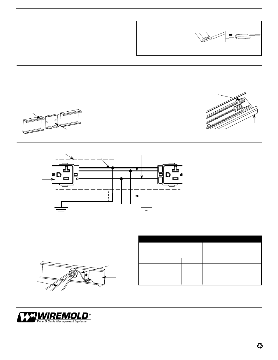
COUPLING TWO PLUGMOLD V2400 WIRED SECTIONS TOGETHER TO EXTEND RUN (USING 2401 COUPLING)
Insert 2401 Coupling halfway into the end of raceway
base. Mount raceway using No. 10 Panhead screws.
Insert second raceway base section onto the
opposite end of the 2401 Coupling. Mount second
raceway section with #10 Panhead
or Flathead wood screws.
Connect black and white harness wires to black
and white feed wires with W30 Wire Connectors*
inserting only conductors of same color in a
connector. See “W30 Wire Connectors…How To
Use”. Connect green grounding wire in harness
to insulated ground conductor in-feed which is
connected directly to service grounding terminal,
using insulated method approved for equipment
grounding connections.
Do not use W30 Wire Connector for this purpose.
Close up unused wire leads at ends of harness
as shown. Do not connect leads together.
V2400B
Base
2401
Coupling
j
R
Wired Section Base
And Cover Grounded
Conventionally
Isolated Ground Service
Grounding Terminal**
*Available separately
Feed Wires
Conventional
Ground
Insulated/Isolated
Receptacle Grounding
Wire (Green)
Black & White
Harness Wires
Orange Receptacle –
All receptacles to
comply with color
identification requirements
CAUTION: Green insulated/isolated grounding
conductor in receptacle harness must be
connected directly to service grounding
terminal through insulated grounding
conductor in-feed. Grounding circuit will not
be isolated if green harness conductor is
connected to Wired Section raceway. Since
unit is not grounded through mounting, a
separate grounding conductor connection
is required.
To preserve insulated/isolated grounding,
insulated ground wire in-feed must be
connected to service grounding terminal,
NOT to panel.
FEEDING WIRED SECTIONS FROM NONMETALLIC-SHEATHED CABLE
Connect feed (black & white wires, and insulated ground wire which
is connected directly to service grounding terminal) to Wired Section
harness. Connect bare (conventional) ground wire to 2409 Ground
Clamp (available separately).
Close up lead ends using
approved method.
Bare Conventional
Ground Wire
2409 Ground Clamp*
V2400 Base
TYPICAL FEED CONNECTION DIAGRAM
**See 2002 NEC, Section 250.96(B)
V2400B
Base
Feed Conduit