Legrand 2000 Series Aluminum Plugmold Multioutlet System User Manual
Al2000 system product applications
Plugmold 2000 Aluminum
Plugmold 2000TR Aluminum
I N S T A L L A T I O N I N S T R U C T I O N S
Installation Instruction No.: 1 009 949 – February 2011
Legrand/Wiremold electrical systems conform to and should be properly
grounded in compliance with requirements of the current National
Electrical Code or codes administered by local authorities.
All electrical products may present a possible shock or fire
hazard if improperly installed or used. Legrand/Wiremold electrical
products may bear the mark of a Nationally Recognized Testing
Laboratory (NRTL) and should be installed in conformance with current
local and/or the National Electrical Code.
IMPORTANT: Please read all instructions
before beginning.
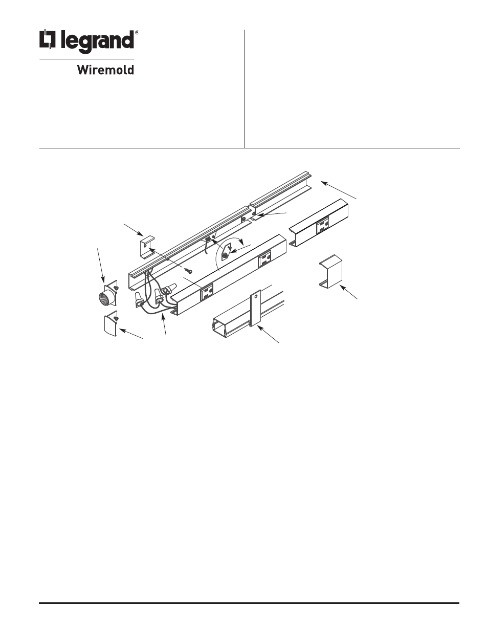
AL2000 SYSTEM PRODUCT APPLICATIONS
TO INSTALL:
1. Bring Feed into Base
a. Remove appropriate 1/2" trade size entrance knockout in base, or attach Feed End Fitting (AL2010A).
2. Install Base Section on Surface
a. Attach base section on mounting surface using AL2003 Spring Mounting Clips, or by drilling 9/32” holes in the base and use #8
set screws. Ensure holes are free from burrs.
b. If required, cut base to length and carefully debur any cut ends before mounting. If cuts have been made to the base, center the
cover section over the mounted base. Locate, mark and cut the cover ends. If the edge of any receptacle falls closer than 1 1/2"
[38mm] from the end of the unit, that receptacle must be cut out to allow sufficient space for the installation of an end fitting.
c. Connect multiple sections together using coupler (AL2001). To install, slide coupling plate into both base sections, center on joint
and tighten locking screws.
d. To install around corners, use appropriate elbows, (AL2011 - 90° Flat Elbow), (AL2017 – Internal Elbow), or (AL2017 - External Elbow)
3. Install Ground Adapter
a. Use Ground Adapter (AL2009) provided to secure ground connection. To relocate, loosen set screw and twist counter clockwise.
Position in between receptacles (to avoid interference) and assemble in reverse order.
4. Install Blank End Fitting (AL2010B)
a. At end of base raceway run, slide blank end fitting in last base sections and secure in place by tightening screw.
5. Connect wired section to feed
a. Connect feed wires to wired raceway sections. It is recommended to stagger connection points to allow room for all connections.
6. Snap raceway cover onto base
a. If necessary, snap receptacle harness into cover making sure to line up receptacle faces with pre-punched holes in the raceway cover.
b. Engage lower edge of cover over the edge of the base. Starting at one end and progressing along the unit, snap in upper edge
of the cover with the heel of the hand. Ensure that wires are pushed completely into the base before assembling the cover to
avoid pinching the wires.
7. Snap on cover clip to cover joint seams where lengths of covers come together.
8. To remove cover, insert removal tool into groove, push down and twist.
NOTE: All mounting methods must result in flush interior surface.
1
6
4
7
8
5
3
2
2