Legrand NM2000 Series Nonmetallic Plugmold Multioutlet System User Manual
Plugmold plus, Nm2000, A1 a2
Wire Size
No. of Wires
THHN/THWN
O.D.
@ 40% Fill
Power Wiring
10 AWG
0.153
15
Without Devices
12 AWG
0.122
31
14 AWG
0.105
45
Power Wiring
10 AWG
0.153
—
With Plugmold Devices
12 AWG
0.122
8*
14 AWG
0.105
8*
*Includes the four conductors of the wiring harness.
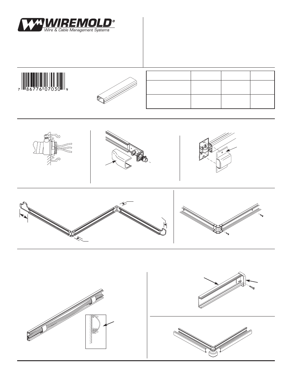
Lay out Raceway path. Determine feed method and location
from figures A, B, and C below.
1
Measure and cut raceway base and cover.
See commmon fittings dimensions below.
2
Install raceway and fittings bases
using No. 8 flathead screws.
3
Install wire in raceway and install wire clips as needed.
Install blank
end fittings with
No. 8 flathead
screws where
needed. Slide
raceway cover
into end fitting.
A1
A2
Field Wired Raceway – NM2000 Series:
A
Snap on raceway and fitting covers.
A3
Wiring Method – Refer to Instructions (A thru E) according to your application.
Fig. A* – Back Feed
Fig. B – End Feed
Fig. C – Feed from Existing Wall Box
1 3/4"
[45mm]
1 5/8" [41mm]
from edge of wall
1" [25mm]
from edge
of wall
1 1/16"
[27mm]
* This method is not recommended if splice area is less
than 4". See Figure B or C for feeding this condition.
NM2051H
NM2010A
NM2000WC
NM2010B
Base
PLUGMOLD PLUS
™
NM2000
I N S T A L L A T I O N I N S T R U C T I O N S
Installation Instruction No.: 41080R4 – Updated June 2003
Wiremold Electrical Systems conform to and should be installed
and properly grounded in compliance with requirements of the
current National Electrical Code, Canadian Electrical Code or
codes administered by local authorities.
All electrical products may represent possible shock or fire hazard
if improperly installed or used. Wiremold electrical products are
UL Listed to U.S. and Canadian safety standards,made for interior
use only, and should be installed in conformance with current local
and/or the National Electrical Code.