Legrand WC Cellular Raceway Systems Terrazzo Rings User Manual
Terrazzo rings
1. Install duct, junction boxes, and accessories according
to the installation instructions provided with each unit.
Level system.
2. The top cover of the junction box should be 1 1/4"
[32mm] from the anticipated finished terrazzo floor
level at this time.
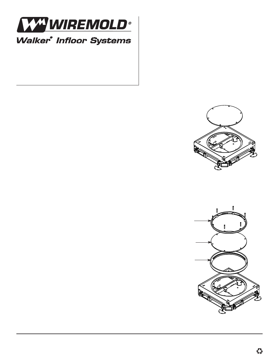
3. Remove the round cover plate from the junction box
(see Figure 1).
4. Set the outer brass ring into the opening in the
junction box cover (see Figure 2).
5. Place the round cover (removed from junction box in
Step 3) into the outer brass ring. Line up screw holes
in cover with holes in the square
cover flange.
6. Place the inner brass ring into the outer ring, on top
of the round cover replaced in Step 5. Line up the
holes in the inner ring with the holes in the
round cover.
7. Replace the original round cover hold-down
screws (#10-24 flathead) with the brass screws
(#10-24 fillister head) provided with the
terrazzo unit.
8. Grease may be spread around the gap between
the inner and outer rings and in the screw holes
to prevent the ingress of any slurry from the
terrazzo mixture.
9. Pour concrete to the desired level. The distance
from the top of the concrete slab to the top of
the terrazzo rings should be equal to the specified
terrazzo thickness.
10. Pour the terrazzo mixture to the top of the brass
terrazzo rings. Fill the inside of the inner ring with
the terrazzo mixture.
11. After curing, grind surface of floor and terrazzo
holder to desired level. Wipe off grease
between rings.
Terrazzo Rings
Cat Nos. RTT4, RTT8, RTT13, and RTT20
INSTALLATION INSTRUCTIONS
Walker
®
electrical systems conform to and should be
properly grounded in compliance with requirements of
the current National Electrical Code or codes adminis-
tered by local authorities.
All electrical products may present a possible shock or
fire hazard if improperly installed or used. Walker elec-
trical products may bear the mark as UL Listed and/or
Classified and should be installed in conformance with
current local and/or the National Electrical Code.
Figure 1
Figure 2
224JR Junction Box
RTT13 Shown
Inner Ring
Round Cover Plate (Removed
from Junction Box in Step 3)
Outer Ring
Walker Systems, Inc.
1000 Innovation Drive, Williamstown, WV 26187
1 000 337 0800
© Copyright 2000 The Wiremold Company All Rights Reserved