Legrand WKD Pro Series Round Flush Cover Plates User Manual
Walkerduct pro series, Round flush cover plates
Walkerduct Pro Series
Round Flush Cover Plates
I N S T A L L A T I O N I N S T R U C T I O N S
Installation Instruction No.: 1 002 970R1 – Updated May 2009
Wiremold/Legrand electrical systems conform to and should
be properly grounded in compliance with requirements of the
current National Electrical Code or codes administered by
local authorities.
All electrical products may present a possible shock or fire
hazard if improperly installed or used. Wiremold/Legrand
electrical products may bear the mark as UL Listed and/or
Classified and should be installed in conformance with
current local and/or the National Electrical Code.
IMPORTANT: Please read all instructions
before beginning.
Products Covered: PSRC9TC, PSRC9AMDTC, PSRC9AMDRTTC, PSRC9FFTC, & PSRC9FF2TC
PRESET LOCATION:
1. Determine location of preset cover by measuring (when layout is
known) or by using an electronic preset finder (Cat. No. 480).
Cut and remove carpeting or tile over preset. Carpet may be
saved for later abandoning.
2. Using a hammer, chip out the concrete from the mud cap cover.
3. Strike the edge of the exposed mud cap with a blade type
screwdriver to deflect the cap inward.
4. Insert the screwdriver along the edge of the preset and pry up
removing the cap.
5. Remove any debris that may have fallen into the preset opening.
6. Grout around preset opening if concrete does not break away cleanly.
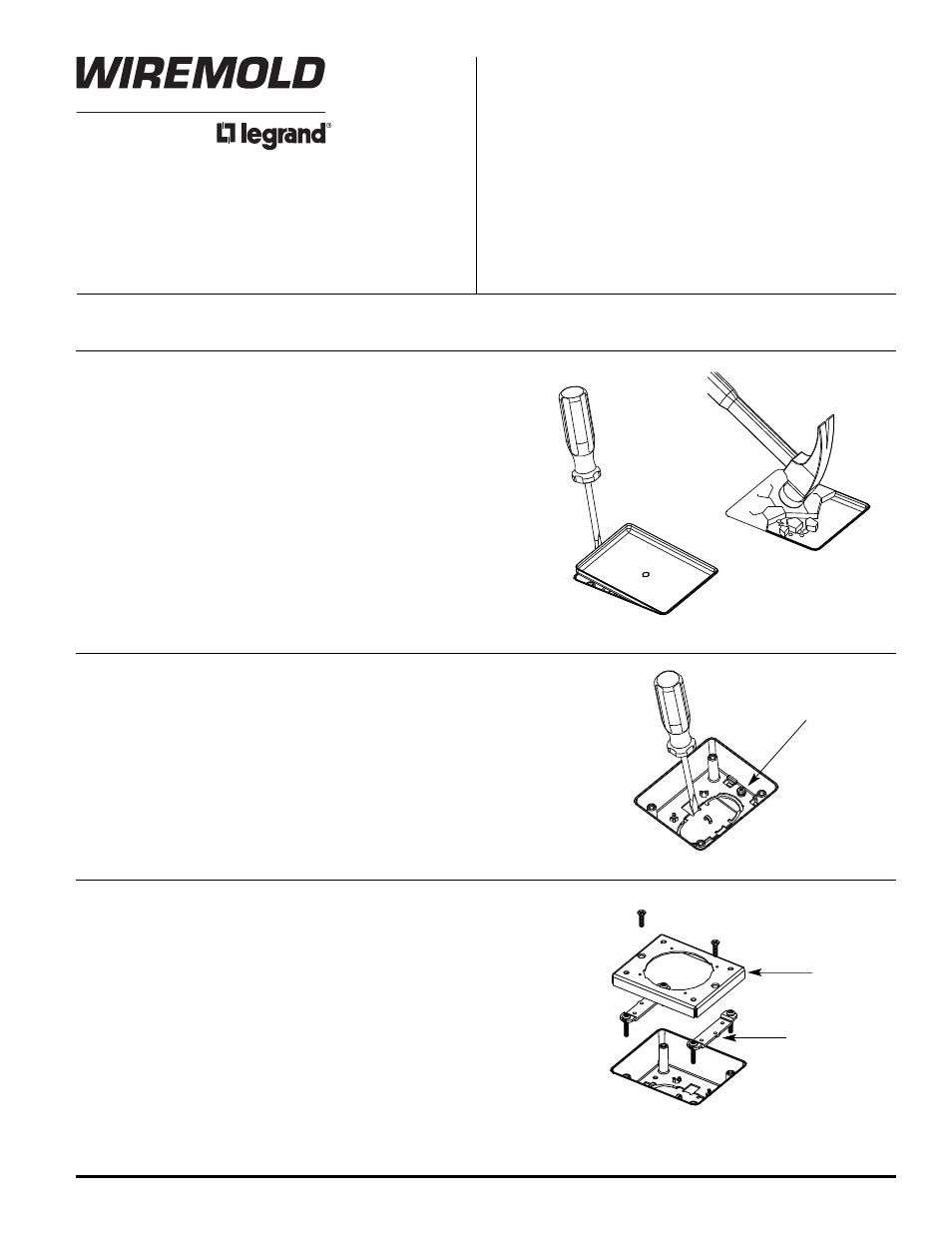
PRESET PREPARATION:
1. Insert a wire hook into the arched opening to prevent the knockout
from falling into the duct.
2. Push screwdriver toward center of the preset, breaking the tabs to
release the knock-out.
3. De-burr the edges after knock-out removal.
4. Tighten the bonding screw in the base of the preset.
CAUTION: Do not operate tile stripper or resurfacing equipment over top of covers. This may result in damage to the finish of the product.
Bonding Screw
COVER ADAPTER INSTALLATION:
1. Install Link Strap to posts in preset as shown. Heads of screws should be
slightly below concrete pour level.
2. Position Adapter Plate over Link Straps as shown.
3. Adjust Link Strap Screws until the adapter plate is flush with finished floor.
4. Secure Adapter Plate to Link Straps using (2) #10 x 3/4” flat head screws.
Adapter Plate
Link Strap
NOTE: To maintain proper ground continuity, tighten
screws to minimum 10 inch pounds.