Legrand WKD Pro Series System User Manual
Page 3
3
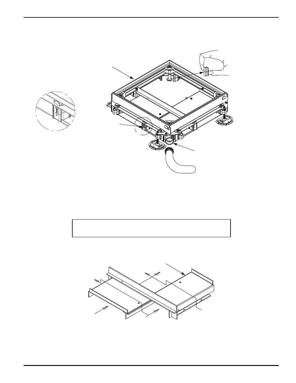
FOUR-WAY JUNCTION BOXES:
1.
Arrows are located on opposing sides of each box to indicate the entrance for feeder raceways. Cables and conductors
entering these sides of the junction box will be routed on the lower level to more easily pass through the junction box. To
maintain proper segregation, all arrows must point in the same direction. (See Detail A)
2.
Where the plans indicate a conduit feed coming into the corner of the junction box, use a Catalog Number 255 - (3/4", 1",
1 1/4", 1 1/2", 2" trade size) conduit adapter. For plastic conduit, install a threaded rigid steel nipple and plastic adapter.
Install a grounding lug inside the junction box. Ground in accordance with the National Electric Code.
3.
The wing shaped end of the plastic spacer at each corner can be removed (except at tunnel locations) to increase wire
pulling area.
4.
Tunnels isolate each service in multiple duct boxes to create a continuous raceway through the box in both directions.
Two Compartment Tunnel
Cat. No. 224JS-1
Junction Box
STEP 1
Detail A
Indicator Arrow
A
STEP 2
Cat. No. 255-3/4
Conduit Adapter
STEP 3
Winged Shaped End
of corner spacer
CAUTION:
The center duct cannot be fed with conduit from any of the box corners. The center
duct may be fed through the center duct openings in any side of the junction box.