Legrand WKD ProSeries Underfloor Duct Adjustable Extension Ring User Manual
Walkerduct, Junction box, Side rail extension
Walkerduct
®
Junction Box
Side Rail Extension
INSTALLATION INSTRUCTIONS
Walker
®
electrical systems conform to and should
be properly grounded in compliance with
requirements of the current National Electrical
Code or codes administered by local authorities.
All electrical products may present a possible
shock or fire hazard if improperly installed or
used. Walker electrical products may bear the
mark as UL Listed and/or Classified and should
be installed in conformance with current local
and/or the National Electrical Code.
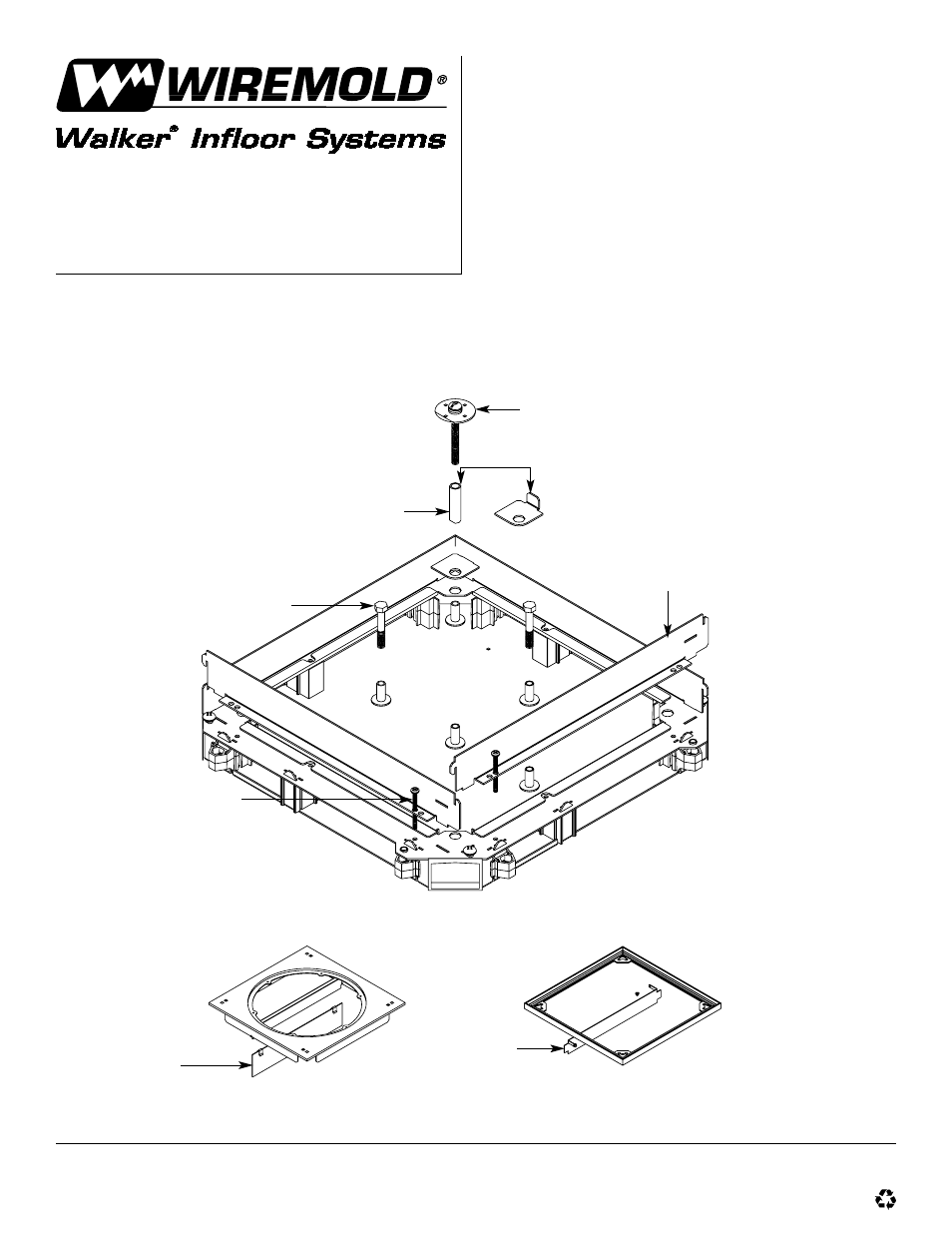
Remove tape, cover plate assembly, aluminum frame
(if applicable), internal leveling screws, existing side
walls, and support bolts (if applicable) from junction
box before starting assembly.
Internal Leveling Screw.
Insert Tube into
Clearance Hole.
Tunnel Not
Shown for Clarity.
#10-24 x 2" PHMS
Screws (8 Required).
Partition Extension
(Attach with Clips).
Reassemble Junction Box Components
and Install New Tape Around Cover Plate.
Replacement Partition
Extensions (Discard
Original Extensions.
Round Cover Plate
Junction Boxes Only.
Square Cover Plate
Junction Boxes Only.
Adjust Bolt Height
so Cover Plate will
be Supported.
Not Used on 1 1/4"
[32mm] and 1 1/2" [38mm]
over Duct Extension Kits.
Replacement Side Wall
Extensions (Discard
Original Extensions.
Walker Systems, Inc.
1000 Innovation Drive, Williamstown, WV 26187
IB0174 0800
© Copyright 2000 The Wiremold Company All Rights Reserved