Legrand WKD ProSeries Underfloor Duct Junction Box Bend Radius Control Inserts Installation User Manual
Adjustable extension ring, Installation instructions
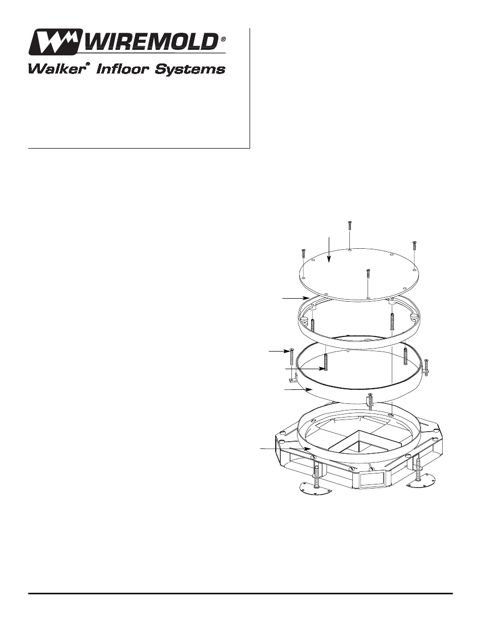
1. Remove cover plate and screws from junction box.
2. Remove zinc adjusting ring by turning adjusting
ring screws clockwise until ring can be lifted away
from screws.
3. Slip extension ring over junction box ring
until bottom rim of extension ring rests
on top of junction box (a soft mallet or
hammer with a block of wood may be
used to help slip extension ring over
junction box ring).
4. Thread the #10-24 screws into the extension
ring leveling tabs and turn clockwise until
top rim of extension ring is at finished
concrete floor level.
5. Place zinc adjusting ring back into position
and adjust to correct height with new leveling
screws provided (refer to chart on back
for correct hardware bag selection).
6. Fasten cover plate to zinc
adjusting ring with the screws
previously removed.
NOTE: Shallow extension ring shown.
Deep extension ring will have
additional junction box ring
(plaster ring) welded to inside.
Adjustable Extension Ring
INSTALLATION INSTRUCTIONS
Walker
®
electrical systems conform to and should
be properly grounded in compliance with require-
ments of the current National Electrical Code or
codes administered by local authorities.
All electrical products may present a possible
shock or fire hazard if improperly installed or
used. Walker electrical products may bear the
mark as UL listed and/or classified and should be
installed in conformance with current local and/or
the National Electrical Code.
Cover Plate
Zinc Adjusting Ring
Adjusting Ring Screws
Extension Ring
(See Note)
Junction Box Ring
(Plaster Ring)
#10-24 Screws