Legrand WKD ProSeries Underfloor Duct Rectangular Floor Box Covers User Manual
Rectangular floor box covers
Rectangular Floor Box Covers
I N S T A L L A T I O N I N S T R U C T I O N S
Installation Instruction No.: 1 003 807R3 – Updated December 2006
Walker
®
electrical systems conform to and should be properly
grounded in compliance with requirements of the current National
Electrical Code or codes administered by local authorities.
All electrical products may present a possible shock or fire
hazard if improperly installed or used. Walker electrical products
may bear the mark as UL Listed and/or Classified and should
be installed in conformance with current local and/or the National
Electrical Code.
IMPORTANT: Please read all instructions
before beginning.
Products Covered:
Polycarbonate Trim Flanges: 817PCC, 827PCC, 837PCC (BLK or BRN)
Brass Trim Flanges: 817C, 827C, 837C (Carpet), 817T, 827T, 837T (Tile) and 817B, 827B, 837B (Combination)
Aluminum Trim Flanges: 818TCAL, 828TCAL, 838TCAL (Tile /Carpet) and 818TAL, 828TAL, 838TAL-880S3, 838TAL-880M3, 838TAL-
880CS3, 838TAL-880CM3 (Tile)
Polycarbonate Activation Plates: 828PR, 828PRGFI, 829PSTC, 829PCK, 829PFL, 829PFLRT (BLK or BRN)
Brass Activation Plates: 828COMTC, 828DLR, 828DPGFITC, 828GFITC, 828R, 828SPTC, 829STC & 829CK Screw Plug Series
Aluminum Activation Plates: 828COMTCAL, 828DLRAL, 828DPGFITCAL, 828GFITCAL, 828R-TCAL & 830CKTCAL Screw Plug Series
BOX/ PRESET LOCATION:
1. Determine location of box or preset by measuring (when
layout is known) or by using an electronic preset finder
(Cat. No. 480). Cut and remove carpeting or tile over box
or preset. Carpet may be saved for later abandoning.
2. Using a hammer, chip out the concrete from the mud
cap cover.
3. Strike the edge of the exposed mud cap with a blade type
screwdriver to deflect the cap inward.
4. Insert the screwdriver along the edge of the preset and pry
up removing the cap.
5. Remove any debris that may have fallen into the enclosure.
6. Grout around the opening if concrete does not break
away cleanly.
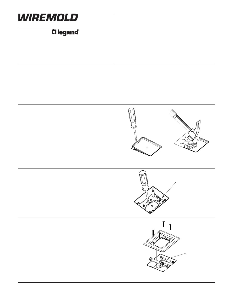
PRO SERIES PRESET PREPARATION:
1. Remove knockout in bottom of preset by inserting a
screwdriver blade into opening as shown.
2. Insert a wire hook into the arched opening to prevent the
knockout from falling into the duct.
3. Push screwdriver toward center of the preset, breaking
the tabs to release the knockout.
4. De-burr the edges after knockout removal and clean all
debris from the raceway.
5. Tighten the bonding screw in the base of the preset
Bonding Screw
PRO SERIES PRESET TRIM FLANGE INSTALLATION:
1. Secure link straps to posts in the preset.
2. Attach the trim flange to the link straps with four #10 flat
head screws. Two lengths of screws are provided to
accommodate variations in floor thickness.
3. If installing on a tile or wood floor, apply a bead of sealant
around the underside of the flange to prevent water
leakage into the preset.
4. For a flush appearance with wood floors, cut an opening
1/8" [3.2mm] deep conforming to the trim ring perimeter
and recess into the floor.
CAT. NO. 817TCAL SHOWN
Link Strap
NOTE: Only “AL”, “B”, or “PCC” Series Trim Flanges may
be installed on Pro Series Presets and Aftersets.