Convia enable walkerflex system installation, Relay dimmer – Legrand Convia Enabled Walkerflex System User Manual
Page 4
4
CONVIA ENABLE WALKERFLEX SYSTEM INSTALLATION
(continued)
Relay Dimmer
The Relay Dimmer Modules are used to
control lighting and other devices, (maximum
20A load) via the Convia Enabled Walkerflex
System. They connect to the Network Hub
to create the Node Bus of the network. Up
to 25 nodes can be connected on a single
Node Bus with a maximum patch cable
length of 1000 feet. Refer to the ConviaNet
Design Guide for more information.
120V SYSTEM
Part
Walkerflex
Number
Phase
Configurations
NRD1A, NRD2A
A
111, 211, 311
NRD1B, NRD2B
B
211, 311
NRD1C, NRD2C
C
311
NRD1F, NRD2F
Field Wired
277V SYSTEM
Part
Walkerflex
Number
Phase
Configurations
LRD1A, LRD2A
A
111, 211, 311
LRD1B, LRD2B
B
211, 311
LRD1C, LRD2C
C
311
LRD1F, LRD2F
Field Wired
Table B – RELAY DIMMER POWER CONFIGURATIONS
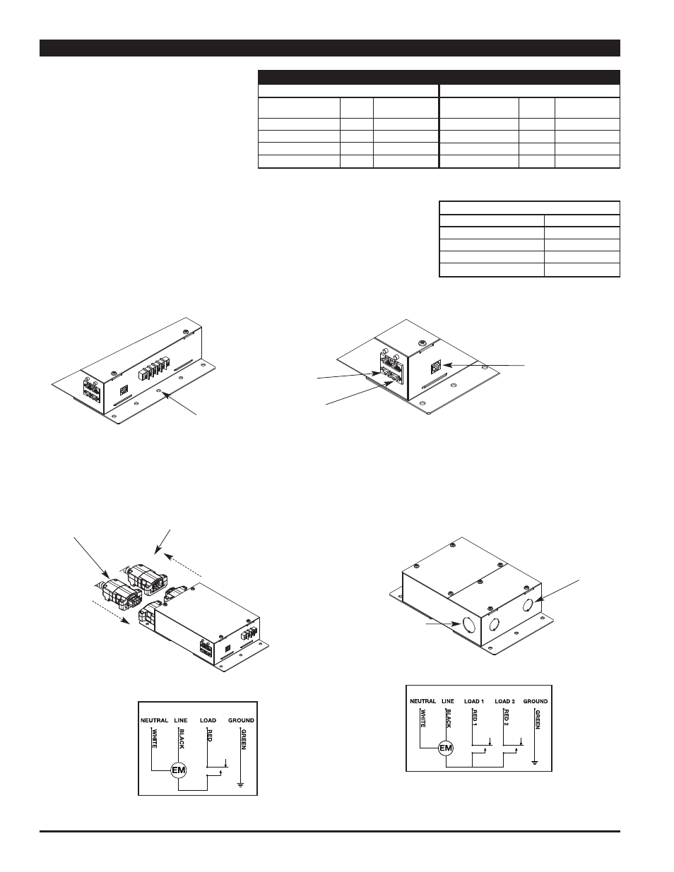
Step 1:
Mount Relay Dimmer securely using
appropriate screws and anchors.
NRD1/LRD1 has one (1) controlled Walkerflex 111 output.
NRD2/LRD2 has two (2) controlled Walkerflex 111 outputs.
APPROVED DIMMING BALLASTS
Manufacturer
Name
Advanced Transformer
Mark
Osram Sylvania
Quiktronic
Universal Technologies
SuperDim
General Electric
UltraMax
NOTE: For proper dimming function, use only approved dimming ballasts.
Additional ballasts are being added as they become available. For
updated ballast information, visit www.wiremold.com. If a qualified
0-10 VDC dimming ballast is not on the list, please contact your
sales representative for verification.
Mounting Holes
Convia Net
(RJ45) Jack for
Accessory Bus
Connections
Convia Net
(RJ45) for
Node Bus
Connections
ConviaIR (RJ11)
Jack for IR
Connections
Step 2:
Connect Power to Relay Dimmers.
For Modular Connection: Connect Convia
Enabled Walkerflex Modular Cable
to modular input and output.
For Field Wired Units: Connect conduit to appropriate
conduit opening and wire per the National
Electric Code. (See Wiring Schematic below
or on product label for connections.
NRD1 Wiring Schematic
Power input coming
from Distribution Box
or main panel
Current Flow
Direction
3/4" Trade Size
Knockout
1/2" Trade Size
Knockout
Power Output going to
light fixture ballasts
Current Flow
Direction
NRD2 Wiring Schematic