Legrand METL520 User Manual
Meterreader, Current monitoring device
Wiremold Electrical Systems conform to and should be installed
and properly grounded in compliance with requirements of the
current National Electrical Code, Canadian Electrical Code or
codes administered by local authorities.
All electrical products may represent possible shock or fire hazard
if improperly installed or used. Wiremold electrical products are UL
Listed, and should be installed in conformance with current local
and/or the National Electrical Code.
MeterReader
®
CURRENT MONITORING DEVICE
I N S T A L L A T I O N I N S T R U C T I O N S
Installation Instruction No.: BK05 – October 2004
RECOMMENDED INSTALLATION INSTRUCTIONS:
Power down and unplug power strip from its source.
Connect the MeterReader CMD unit to the source, and plug
in the power strip to the connector side. Using supplied 7'
[2.1m] patch cable, connect one end to the remote display
device and the other into the RJ45 on the MeterReader unit.
Power up the power strip.
The Wiremold MeterReader
®
Current Monitoring Devices are recognized by Underwriters Laboratories, Inc
and available in four standard plug and connector sets: L5-20; L5-30; L6-20 and L6-30.
The ammeter display provides a three-digit true RMS (+/-0.2A) LCD readout from 0 – 30Amps with backlighting
for easier visibility in a darkened environment.
The MeterReader is rated for the following Environmental Conditions:
• Indoor use only
• Temperatures from 5° C – 40° C [40° F – 100° F].
• Altitude up to 6550ft. [2000m]
• Pollution degree2, CAT II
• Maximum relative humidity 80% up to 31° C [88° F]
decreasing linearly to 50% relative humidity at 40° C [100° F].
j
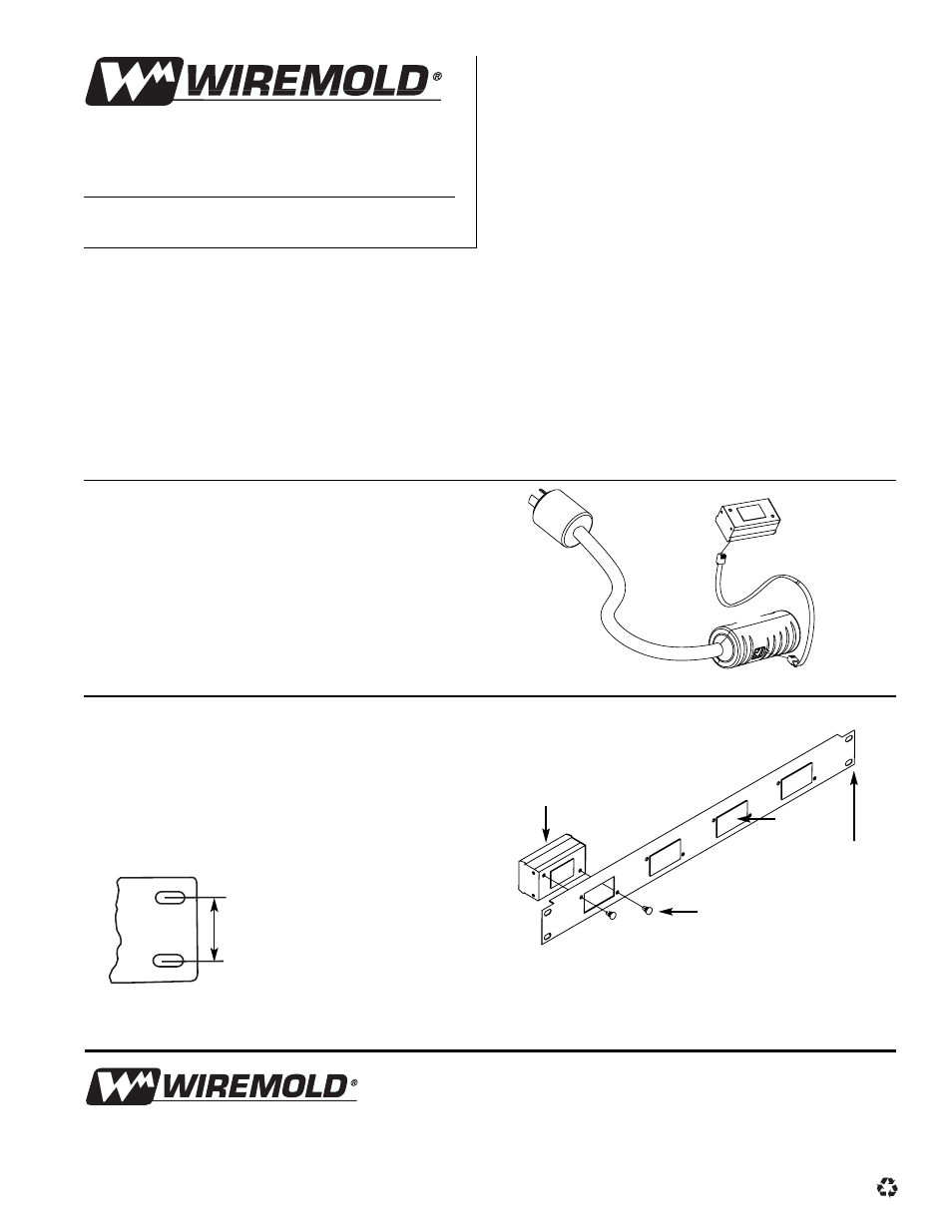
Remove black insert and push pins to clear the desired
display location. Use a flat screw driver to gently pry up
the push pin head followed by the push pin body so they
are not separated.
Line up the remote display box with the cleared holes in
the rack mount face plate and insert the push pins through
the pin holes as indicated. Once secured, install the face
plate into your 19" [483mm] rack via the closed slots.
(Closed Slots
for Rigidity)
Designed in Accordance with E. I. A. Standards
The Wiremold Company
U.S. and International:
60 Woodlawn Street • West Hartford, CT 06110
1-800-621-0049 • FAX 860-232-2062 • Outside U.S. 860-233-6251
Canada:
850 Gartshore Street • Fergus, Ontario N1M 2W8
1-800-741-7957 • FAX 519-843-5980
BK05 – October 2004 – For latest specs visit www.wiremold.com
© Copyright 2004 The Wiremold Company All Rights Reserved
Questions? Call Technical Support at 1-800-Sentrex.
RECOMMENDED INSTALLATION INSTRUCTIONS – Remote Display:
Remote Display
Push Pins
Insert
Rack Mount
Faceplate