Legrand AL5200 Series Aluminum Raceway User Manual
Al5200 aluminum raceway installation instructions
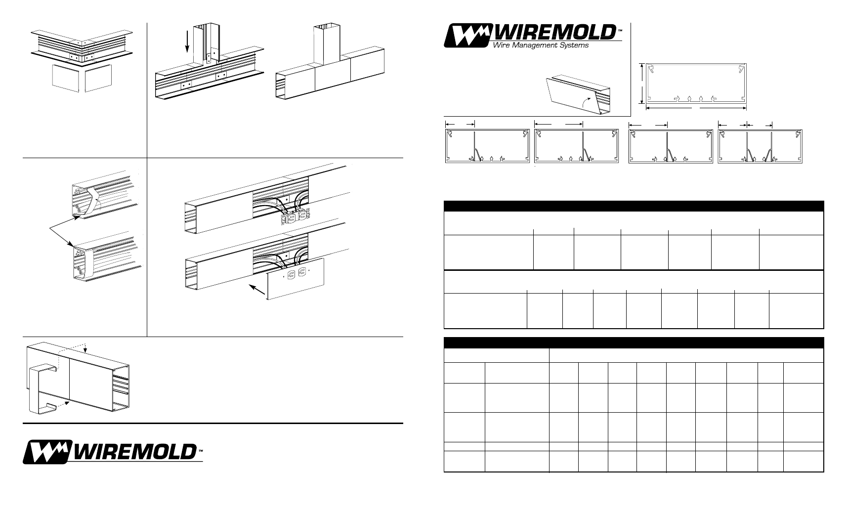
AL5200 ALUMINUM RACEWAY
Installation
Instructions
2"
5"
8.50
sq. in.
Raceway may be configured in single or multiple channels in sev-
eral versatile ways to accommodate power, data or telecommuni-
cations wiring.
NOTE: Cross-sectional area of each compartment indicated.
2 3/16"
3.90
sq. in.
4.50
sq. in.
1 5/8"
2.85
sq. in.
2.85
sq. in.
2.40
sq. in.
1 1/2"
1 5/8"
2.85
sq. in.
5.50
sq. in.
2 3/4"
4.80
sq. in.
3.50
sq. in.
Wiremold Electrical Systems conform with, and should be installed and properly grounded in compliance with requirements of the current
National Electrical Code or codes administered by local authorities. All electrical products may represent a possible shock or fire hazard if improp-
erly installed or used. Wiremold electrical products are UL listed, made for interior use and should be installed by qualified electrical people in
conformance with current local and/or the National Electrical Code.
CAPACITY OF CROSS SECTIONAL AREA
WITH DUPLEX DEVICE (1.34 Sq. In.)
WIRE TYPE
3.5"
3.9"
4.5"
4.8"
5.5"
8.5"
THWN/THHN #6
16
19
24
26
32
55
#8
23
27
34
37
44
76
#10
47
55
68
75
90
155
#12
74
87
108
118
142
244
#14
99
117
145
159
191
329
CAPACITY OF CROSS SECTIONAL AREA
WITHOUT DEVICES
WIRE TYPE
2.4"
2.85"
3.5"
3.9"
4.5"
4.8"
5.5"
8.5"
THWN/THHN #6
18
22
27
30
34
37
42
65
#8
25
30
37
42
48
51
59
91
#10
52
62
76
84
98
104
119
184
#12
82
97
119
133
154
164
188
290
#14
110
131
161
179
207
220
253
391
AL5200 RACEWAY WIRE FILL CAPACITIES FOR POWER
At 90° Outside Corner, position AL5218
External Elbow at end of AL5200B Base.
Slide other base section to other end of
AL5218. Center couplings on joints and
tighten screws. After wiring system,
snap on AL5218 mitered covers.
For retaining wires in long raceway
runs, snap-in AL5200WC Series Wire
Clips into AL5200B Base as required.
Snap AL5206 Cover Clip over joints
in either AL5200B Base or AL5200C
Cover sections.
AL5215 Tee (shown above) and Al5216 Cross: Position fitting at end of
AL5200B Base. Install other base sections to other ends of the fitting. Center
couplings on joints and tighten screws. Install fitting covers after wiring.
AL5200WC
The Wiremold Company
In U.S.:
60 Woodlawn Street • West Hartford, CT 06133-2500
1-800-621-0049 • FAX 860-232-2062
In Canada:
850 Gartshore Street • Fergus, Ontario N1M 2W8
1-800-741-7957 • FAX 519-843-5980
41045 896
©1996 The Wiremold Company
For AL5246P Series Device Plates, install wiring to devices as required. Attach
devices to plate using #6 screws and "Keps" nuts provided. Snap device plate onto
AL5200B raceway base.
CAPACITY OF CROSS SECTION AREA*
CABLE/WIRE SIZE
O.D.
2.4"
2.85"
3.5"
3.9"
4.5"
4.8"
5.5"
8.5"
UNSHIELDED
4-Pair, 24 AWG, Cat.5
0.220
19
22
27
31
35
38
43
67
TWISTED
4-Pair, 24 AWG, Cat.3
0.190
25
30
37
41
47
50
58
90
PAIR (UTP)
TELEPHONE
2-Pair, 24 AWG
0.140
47
55
68
76
87
93
107
165
3-Pair, 24 AWG
0.150
41
48
59
66
76
81
93
144
4-Pair, 24 AWG
0.190
25
30
37
41
47
51
58
90
25-Pair, 24 AWG
0.410
5
6
8
9
10
11
12
19
COAXIAL
RG58/U 18 Gage
0.195
24
28
35
39
45
48
55
85
CABLES
RG59/U 22 Gage
0.242
15
18
23
25
29
31
36
55
RG62A/U 20 Gage
0.242
15
18
23
25
29
31
36
55
RG6/U 22 Gage
0.270
12
15
18
20
23
25
29
44
TWINAXIAL
100 Ohm
0.330
8
10
12
13
16
17
19
30
SHIELDED
TYPE 1
0.390
6
7
9
10
11
12
14
21
TWISTED
TYPE 2
0.465
4
5
6
7
8
8
9
15
PAIR (STP)
TYPE 9
0.275
12
15
18
20
23
25
28
44
AL5200 RACEWAY WIRE FILL CAPACITIES FOR DATA/COMMUNICATIONS
1
1
Capacity range is calculated at 40% of raceway areas based on pending changes to the Commercial Buildings Standard for Telecommunication Pathways and Spaces,
EIA/TIA-569. Caution: Capacity for radial bonds reduce to 20% of raceway area.