Legrand Wallduct Medical Raceway System Bodies User Manual
Wallduct bodies & fittings, Installation instructions
Wallduct Bodies & Fittings
INSTALLATION INSTRUCTIONS
Installation Instruction No.: 1 002 623 – January 2003
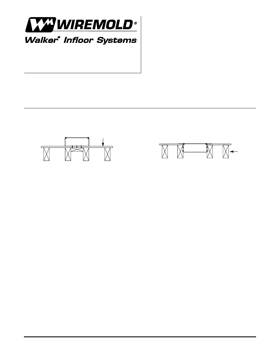
Wall Surface
Thru Surface Wallduct
Thru Flush Wallduct
Walker
®
electrical systems conform to and should be properly
grounded in compliance with requirements of the current National
Electrical Code or codes administered by local authorities.
All electrical products may present a possible shock or fire
hazard if improperly installed or used. Walker electrical products
may bear the mark as UL Listed and/or Classified and should
be installed in conformance with current local and/or the National
Electrical Code.
IMPORTANT – PLEASE READ ALL INSTRUCTIONS BEFORE BEGINNING.
Products Covered:
Steel and aluminum raceway bodies, fittings, and accessories with catalog numbers beginning with the
following prefix: WD, AWD, CP, ACP, VA, or AVA.
Wall
Stud
Raceway and fittings may be mounted directly to a wall / ceiling surface, or mounted within the wall / ceiling so
that the cover plate is flush with the mounting surface (see illustration below).
Mounting means and hardware are not provided. Raceway and fittings must be secured to the mounting surface
at intervals not exceeding 4 feet [1.2m] when wall mounted vertically or horizontally with a minimum of 4 drywall
screws with a length of 2.00" [5.08cm] with a coarse thread pattern. A spacing of 2 feet [.610m] is recommended.
The portion of the fastener that resides inside the raceway must be free of sharp edges or any surfaces that may
abrade the internal cabling. Mounting holes must be field drilled into the raceway and fittings. Make sure screws
applied meet your specific load applications and that the mounting surface material will support the load of the
raceway and fittings, and the additional load of the internal cabling. When mounting from a ceiling, consult
manufacturer of support means to make sure load applied can be properly supported. In order to do this you
must calculate the wire and duct weight over the desired distance between supports.
When assembling adjacent sections of raceway and fittings together using the coupling angles and hole locations
provided, screws must be tightened to a torque of 35 inch-pounds [3.953 Nm]. Use a #18 drill, diameter of .170"
[4.31mm] for field drilled hole locations where #10-32 taptite screws are being used. Suggested torque value for
taptite screws is 25 inch-pounds [2.823Nm]. For coverplates or other locations where palnut clips are to be used,
a hole of 9/32" [7.143mm] is required. Cover plates must be secured to the raceway and fittings with the screws
provided to a torque value of 30 inch-pounds [3.388 Nm].
All field cut edges or corners must be filed smooth or a grommet added to prevent damage to internal cabling and
personal injury. The installer must take special care when installing internal tunneling and partitions to prevent any
gaps or openings greater than 1/16" [1.59mm] in width.
Raceway and fittings must be grounded in accordance to the NEC and any other local codes that apply. Any paint
that is applied to the raceway must be removed in the locations where the grounding means (not provided by Walker
Systems, Inc.) is attached. Raceway system is intended for power conductors 4/0 or smaller and circuits operating
at potentials not exceeding 600 volts between conductors.