Legrand 5500 Series Large Capacity Raceway User Manual
Ij h f, Installation instruction, 5500 series
6
11
/
16
"
A
8.142 Sq. In
1
3
/
4
"
5500 Series
Surface
Nonmetallic Raceway System
Installation Instruction
Wiremold Electrical Systems conform to and should be installed and properly
grounded in compliance with requirements of the current National Electrical
Code, Canadian Electrical Code or codes administered by local authorities.
All electrical products may represent possible shock or fire hazard if improperly
installed or used. Wiremold electrical products are UL listed, made for interior
use only and should be installed in conformance with current local and/or the
National Electrical Code.
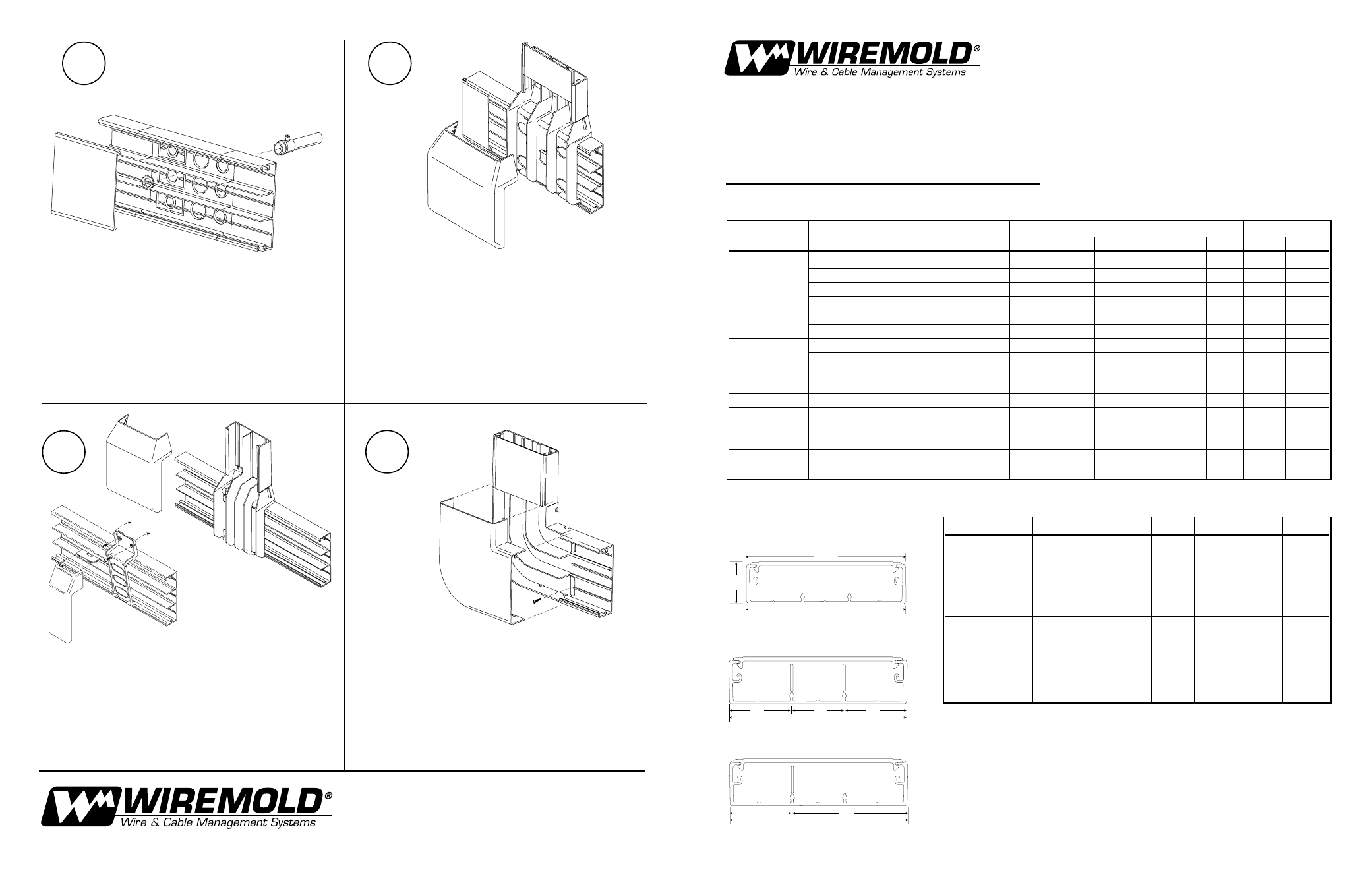
5514A
Use this Fitting to back feed from an existing wall box, or to feed from
1
/
2
",
3
/
4
", and 1 inch conduit; score K.O with knife, then punch out.
5515
Punch out appropriate hole in the Tee Fitting Base, and snap to Raceway
Base; screw down to wall. Assemble Raceway covers to Base and then
snap on Tee cover overlapping R/W covers.
Punch out appropriate hole in base and snap to raceway base: screw down
to wall. The 5574 is used to feed 400, 800, 2300 raceways. Remove proper
twistout by first scoring with knife and then twisting. The 5574A is used to
feed 5400 Series Raceway. Assemble raceway covers to base and then
snap on the 5574 or 5574A cover overlapping the raceway covers.
5511
Mount flat elbow as shown; Assemble Raceway covers first, Then elbow
cover.
Communications and Signal Capacity
B
D
B
B
2.643
Sq. In
2.643
Sq. In
2.643
Sq. In
C
B
D
I
J
H
F
40614 896
©1996 The Wiremold Company
The Wiremold Company
60 Woodlawn Street, P.O.Box 332500
West Hartford, CT 06110-2500
Tel (860) 233-6251
Fax 860-232-2062
2.643
Sq. In.
5.286
Sq. In.
5574
5574A
Cable Type
Category/Designation
Typical
20% Fill
20% Fill
Undivided
O.D. (in.)
A
B
C
A
B
C
20%
40%
Unshielded
4-pair, 24 AWG Cat 5 UTP
0.22
42
13
28
85
27
56
42
85
Twisted Pair
4-pair, 24 AWG Cat 3 UTP
0.19
57
18
38
114
37
76
57
114
Telephone
2-pair, 24 AWG
0.14
105
34
70
211
68
140
105
211
3-pair, 24 AWG
0.15
92
29
61
184
59
122
92
184
4-pair, 24 AWG
0.19
57
18
38
114
37
76
57
114
25-pair, 24 AWG
0.41
12
4
8
24
8
16
12
24
Coaxial
RG58/U
0.195
54
17
36
109
35
72
54
109
RG59/U
0.242
35
11
23
70
22
46
35
70
RG62/U
0.242
35
11
23
70
22
46
35
70
RG6/U
0.27
28
9
18
56
18
37
28
56
Twinaxial
100 Ohm
0.33
19
6
12
38
12
25
19
38
Shielded Type
1
0.39
13
4
9
27
8
18
13
27
Twisted Pair
Type 2
0.465
9
3
6
19
6
12
9
19
(STP)
Type 3
0.245
34
11
22
69
22
45
34
69
Fiber Optic
Two Stranded (Duplex)
Multimode, 62.5/125 um
0.19
57
18
38
114
37
76
57
114
Wire Capacity 5500 Raceway
Wire Size THHN, THWN
A
B
C
D
Power Wiring
6 AWG
41
12
12
24
without Devices
8 AWG
60
13
13
28
10 AWG
72
35
35
59
12 AWG
65
33
33
63
14 AWG
55
41
41
54
Power Wiring
6 AWG
41
6
6
24
with Devices
8 AWG
60
8
8
28
10 AWG
72
16
16
54
12 AWG
65
26
26
63
14 AWG
55
34
34
54
Wire capacity is reduced to allow for proper conductor bend radius and maximum per-
missible heat rise.
1. A, B, C, D are areas of usage.
2. No one compartment may exceed capacity as specified in area B and C.
3. Total raceway max. wire capacity may not exceed fill as specified in area A or B,
depending on configuration being used.