Legrand 500 Small Raceway Laser Level User Manual
Laser level & cutting guide, Cutting guide instructions, Laser level instructions
Laser Level & Cutting Guide
I N S T R U C T I O N S
Installation Instruction No.: 1 009 182 – July 2010
Legrand/Wiremold electrical systems conform to and should be properly
grounded in compliance with requirements of the current National
Electrical Code or codes administered by local authorities.
All electrical products may present a possible shock or fire
hazard if improperly installed or used. Legrand/Wiremold electrical
products may bear the mark of a Nationally Recognized Testing
Laboratory (NRTL) and should be installed in conformance with current
local and/or the National Electrical Code.
IMPORTANT: Please read all instructions
before beginning.
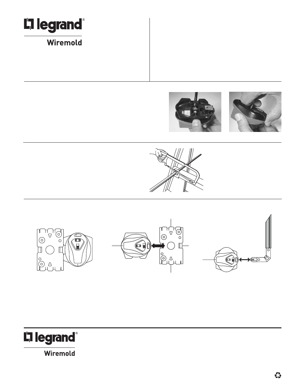
1. Place guide with slot facing up onto a ladder step.
2. Use thumbscrew to tighten in place.
3. Insert raceway, conduit, or threaded rod into slot.
4. Insert saw blade into guide and cut the product.
CUTTING GUIDE INSTRUCTIONS
Laser level will work with both Raceway fittings and Boxes. It can also be used
on other magnetic surfaces or sheetrock with supplied push pins.
LASER LEVEL INSTRUCTIONS
1. Rotate laser base until you feel it lock into laser level detents.
2. Use the side of the laser base to level the box base to the wall (See Figure 1).
3. Rotate laser base 180 degrees and slide laser level onto the box tongue (See Figure 2).
4. Turn on laser and rotate to establish a level line using laser level bubble.
5. Use laser level line as a guide to mark holes for raceway mounting clips.
6. Slide laser level onto the fitting tongue (See Figure 3).
7. Repeat step 5.
Figure 1
Figure 2
Figure 3
WIREMOLD
U.S. and International:
60 Woodlawn Street • West Hartford, CT 06110
1-800-621-0049 • FAX 860-232-2062 • Outside U.S.: 860-233-6251
Canada:
570 Applewood Crescent • Vaughan, Ontario L4K 4B4
1-800-723-5175 • FAX 905-738-9721
Made in China
1 009 182 0710
© Copyright 2010 Legrand/Wiremold All Rights Reserved
1. Verify that laser switch is in the OFF position.
1. Separate base plate from the laser body by removing the
center screw. (Figure 1)
2. Slide the battery cover off by gripping and sliding the
center protrusion toward you. (Figure 2)
3. Install two (2) AAA batteries and reassemble.
BATTERY INSTALLATION
Figure 1
Figure 2