Legrand NE AnySize Multi-Compartment Surface Metal Raceway User Manual
Anysize, Multi-compartment, Surface metal raceway
AnySize
™
Multi-Compartment
Surface Metal Raceway
I N S TA L L AT I O N I N S T R U C T I O N S
All Wiremold electrical products, unless specifically noted, are
listed by Underwriters’ Laboratories, Inc. and conform to U.S.
Federal Specification W-C-582. They comply with the National
Electrical Code. Products designed primarily for use in telephone or
communications wiring and tools normally do not require UL
or cUL listing. Most products are cUL listed in compliance with
the Canadian Electrical Code. All products must be installed in
a manner consistent with applicable electrical codes. Wiremold
Surface Raceway is UL and cUL listed by Underwriters’
Laboratories, Inc. (File #E4376 [Raceway] and E41751 [Fittings]).
This product is in compliance with the National Electrical Code and
the Canadian Electrical Code.
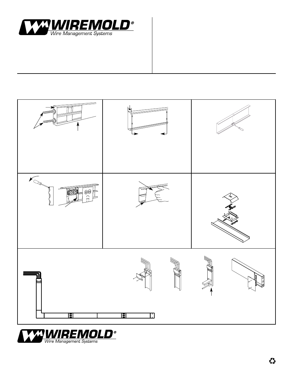
See the typical basic system (illustrated below) for installation details. In general, the following procedure
for installing AnySize Raceway is recommended.
Starting at feed connection, install base sections
over entire run. Butt ends of sections and install
couplings. Cut base sections to length as required
for connection of fitting bases. Determine the
method of feeding raceway: raceway base or wall
box connector for back feed, end blanks (shown),
entrance end fittings, or panel connector for end feed.
Assemble devices and device covers in base.
To install device plates, snap device straps in base.
Wire device and assemble to straps. Snap device
plate over base and device. For deep device plates
or offset device plates fasten to raceway base by
screwing into device brackets in raceway base.
Cut cover sections to length as necessary and snap
onto base. It is recommended that covers overlap
base joint. Use pre-cut cover, or cut cover to fit
between device plates. Snap in place as shown.
Continue along entire run.
To mount base to surface, remove mounting
knockouts as required. Mount base with No. 8
flat head fasteners.
Install wiring in base and wire devices. To couple
lengths of base or fittings, butt the adjacent base
sections together and insert one coupling centered
over the splice. Tighten the set screws. Repeat the
process on the other side of the base.
1
2
3
4
5
Device Mounting Straps
Snap Cover onto Base
Engage one leg of Cover on Base
Typical Basic System:
End Blank
Conduit
Base
Depth
24" [610mm]
(approx.)
Bottom Inserts First
Typical Tamper Resistant Installation
A. Complete instructions 1 to 3.
B. Add Covers progressively from access point to
other end, utilizing instructions 4 and 5 as needed.
C. Repeat (ii) and (iii) as required sliding tamper-
resistant brackets and covers into place. Bracket
slides into notch in cover flange
D. Any cut covers will require replacement of the
tamper-resistant notch using NE610 tool.
E. Tighten all screws securely.
(i)
(ii)
(iii)
(iv)
NE1407 Deep Device
Plate Installation
The Wiremold Company
U.S. and International:
60 Woodlawn Street • West Hartford, CT 06110
1-800-621-0049 • Outside U.S. 860 233-6251 • FAX 860-232-2062
In Canada:
850 Gartshore Street • Fergus, Ontario N1M 2W8
1-800-741-7957 • FAX 519-843-5980
INS00009R1 – Updated June 2001 – For latest specs visit www.wiremold.com
© Copyright 2001 The Wiremold Company All Rights Reserved
j