Legrand TM1542TRCF User Manual
Trademaster, Floorbox and tamper resistant finishing kit
TradeMaster
®
Floorbox Description
The TM1542BOX for installation of electrical receptacles in wooden floors, where
required by National Electrical Code Standards, or for aesthetic preference. The
round floorbox is finished by a TM1542 finishing kit, (sold separately). Floorbox
can also accommodate low voltage wires, through the compartments provided.
Application
Floorbox is used to provide a place for electrical power in the floor, in an application
where it is difficult or impossible to provide power in the wall, but where it is required
by the NEC. The box can also be used to provide electrical power where it is desired
in the middle of the room, without the use of extension cords. The box can also be
used to provide access to low voltage communication wires.
Tamper-Resistant Finishing Kit Description and Application
The finishing kit is used to mount the electrical outlet in the TradeMaster
®
Floorbox,
(sold separately). The plastic cover is available in four different colors to blend into
your décor. The brass cover is available in two designs: A flush-mount version for
hardwood floors, and a raised flange version for carpeting, linoleum, etc. the outlet
is covered by a door which can be removed and replaced. When the outlet is not in
use, the door shuts for a flush finish. These covers are designed to be used only
with the TM1542BOX TradeMaster
®
Floorbox.
A 15 Amp, 125 Volt Tamper-Resistant outlet is included with the finishing kit. This
outlet meets NEC 406.11 requirment for Tamper-Resistant receptacles in
dwellings. The kit can be used with any decorator style device, such as a GFCI,
TVSS, or low voltage device. Low Voltage communication wires can also be
installed outside of the line voltage area by drilling holes in the cover as described
in these instructions.
AVAILABLE CATALOG #’s
Catalog #
Description
TM1542BOX
Round Wood Floorbox
TM1542TRBR
Brown Finishing Kit with Brown
15 Amp, 125 Volt Tamper-Resistant Outlet
TM1542TRW
White Finishing Kit with White
15 Amp, 125 Volt Tamper-Resistant Outlet
TM1542TRLA
Light Almond Finishing Kit with Light Almond
15 Amp, 125 Volt Tamper-Resistant Outlet
TM1542TRGRY
Gray/Paintable Finishing Kit with Gray
15 Amp, 125 Volt Tamper-Resistant Outlet
TM1542TRCF
Brass Finishing Kit, Carpet Flange with Brown
15 Amp, 125 Volt Tamper-Resistant Outlet
TM1542TRFM
Brass Finishing Kit, Flush Mount with Brown
15 Amp, 125 Volt Tamper-Resistant Outlet
Warning: Turn off all power to circuit before installing this device. Improper wiring
of any electrical device can cause serious injury or death. These wiring devices
should only be installed by an Electrician or other qualified person. Connect only
copper or copper-clad wire to the device in this package. Do not connect
aluminum wire to this device.
Wiring and floorbox installation must comply with the National Electrical
Code, and all applicable local codes.
As with any floor box, leaving the door open while not in use may result
in contamination of the installed wiring device, causing it to fail.
TradeMaster
®
TM1542-BOX
I. Box Installation
1. Determine the box location
2. Cut a 4 3/4" diameter hole into the sub-floor
3. Secure the TM1542-BOX to the sub-floor with the three screws provided.
(See Figure 1)
4. Lay finish floor over the sub-floor. The hole placed in the finish floor
cannot exceed 6" in diameter. Larger hole will not be covered by the
finishing kit.
(See Figure 2)
II. Wire Installation
1. Pull the line voltage conductors through the boxʼs auto clamp openings
or the knockout openings located near the bottom of the box. If
knockouts are used, wire clamps are required (not supplied).
2. Cut line voltage wires, leaving a minimum length of 9" above the opening
of the box.
3. Low and line voltage cannot be installed in the same cavity per the
National Electrical Code. (See Figure 3)
TradeMaster
®
Tamper-Resistant Finishing Kit
I. Cover installation
Plastic Covers: TM1542TRBR, TM1542TRW, TM1542TRLA,
TM1542TRGRY
1. Optional low voltage feed-through applications: (See Figure 4)
a. Drill 3/8" diameter hole(s) in the cover. Drill hole locations are marked
on the bottom side of the cover.
b. Insert grommet(s) into the drilled holes and route the low voltage
communication wire(s) through the grommet opening(s).
2. Insert the cover into TM1542-BOX opening.
3. Fasten the adapter to the box with the four screws provided. Do not tighten
the screws to the point where the cover distorts (approx. 12 in-lbs).
Brass Covers: TM1542TRFM, TM1542TRCF
1. Optional low voltage feed-through applications: (See Figure 4)
a. Drill 3/8" diameter hole(s) in the brass flange. Drill hole locations are
indented on the bottom side of the brass flange.
b. Insert grommet(s) into the drilled holes and route the low voltage
communication wire(s) through the grommet opening(s).
2. Insert the adapter into the center of the flange (only if separated from
flange).
3. Fasten the adapter to the box with the four screws provided. Do not tighten
the screws to the point where the adapter distorts (approx. 12 in-lbs).
Note: TM1542TRFM cannot be used with finished floor thickness of less than 3/8
".
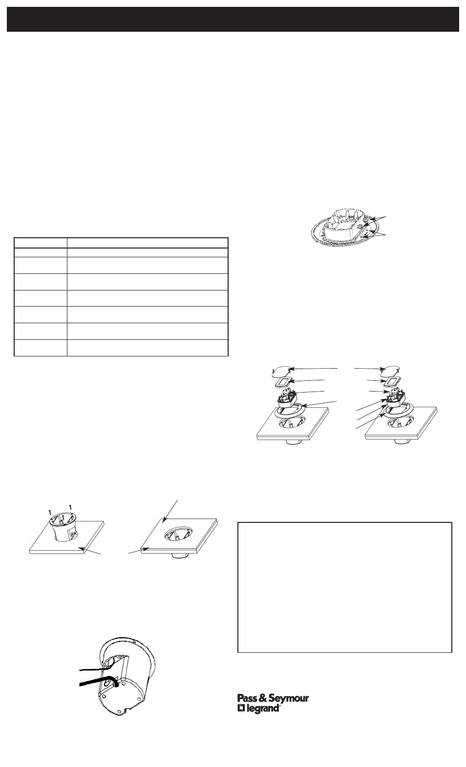
II. Receptacle Installation
Warning: Turn off all power to circuit before installing this device. Improper
wiring of any electrical device can cause serious injury or death. These wiring
devices should only be installed by an Electrician or other qualified person.
Connect only copper or copper-clad wire to the device in this package. Do not
connect aluminum wire to this device.
Plastic Covers: TM1542TRBR, TM1542TRW, TM1542TRLA,
TM1542TRGRY
(See Figure 5)
1. If using the included outlet, strip conductors to 3/4". If using a different
device, follow instructions on package.
2. Terminate Ground, Neutral, and Hot wires in that order.
3. Install (attach) outlet to the cover with the two screws provided.
4. Snap the decorator cover over the outlet face.
5. Replace the door if removed during installation with a snap fit at the hinge area.
Brass Covers: TM1542TRFM, TM1542TRCF
(See Figure 6)
1. If using the included outlet, strip conductors to 3/4". If using a different
device, follow instructions on the outlet package.
2. Terminate Ground, Neutral, and Hot wires in that order.
3. Install (attach) outlet to the cover with the two screws provided.
4. Snap the decorator cover over the outlet face.
5. Replace the door to the flange with the two screws provided.
Limited One Year Warranty
Pass & Seymour will remedy any defect in workmanship or material in Pass & Seymourʼs products
which may develop under proper and normal use within one year from date of purchase by a customer:
(1) by repair or replacement, or, at Pass & Seymourʼs option, (2) by return of an amount equal to
consumerʼs purchase price. Such remedy is IN LIEU OF ANY AND ALL EXPRESSED OR IMPLIED
WARRANTIES OF MERCHANTABILITY OR FITNESS FOR A PARTICULAR PURPOSE. Such remedy
by Pass & Seymour does not include or cover cost of labor for removal or reinstallation of the product.
ALL OTHER FURTHER ELEMENTS OF DAMAGE (INCIDENTAL OR CONSEQUENTIAL DAMAGES)
FOR BREACH OF ANY AND ALL EXPRESSED OR IMPLIED WARRANTIES INCLUDING
WARRANTIES OF MERCHANTABILITY OR FITNESS FOR A PARTICULAR PURPOSE ARE
EXCLUDED HEREBY. (Some states do not allow disclaimer or exclusion or limitation of incidental or
consequential damages, so the above disclaimers and limitation or exclusion may not apply to you. ANY
IMPLIED WARRANTIES INCLUDING WHERE REQUIRED WARRANTIES OF MERCHANTABILITY
OR FITNESS FOR A PARTICULAR PURPOSE SHALL BE LIMITED TO THE ONE YEAR PERIOD SET
FORTH ABOVE. (Some states do not allow limitations on how long implied warranty lasts, so the above
limitation may not apply to you.)
To insure safety, all repairs to Pass & Seymour products must be made by Pass & Seymour, or under
specific direction. Procedure to obtain performance of any warranty obligation is as follows: (1) Contact
Pass & Seymour, Syracuse, NY 13221, for instructions concerning return or repair; (2) return the
product to Pass & Seymour, postage paid, with your name and address and a written description of
the installation or use of the Pass & Seymour product, and the observed defects or failure to operate,
or other claimed basis for dissatisfaction
.
Floorbox and Tamper Resistant Finishing Kit
Installation Instructions
Figure 3
Low Voltage
Line Voltage
Figure 4
Grommets
Drill Hole
Locations
Figure 1
Sub floor
Figure 2
Finish floor
(Opening must be
less than 6" dia.)
Door
Decorator Cover
Tamper-Resistant
Receptacle
Cover
O Ring
Adapter
Flange
©2010 Pass & Seymour/Legrand
P.O. Box 4822, Syracuse, NY 13221
P/N 340906
Figure 5
Figure 6