Legrand 1595SWT User Manual
Combination switch/gfci outlet, Switch installation instructions for, Wiring diagram a1
The Pass and Seymour Combination Switch/ GFCI (catalog number
1595SWT and 15952SWT) are devices that offer several installation
options. Before attempting the installation the installer must first review
and select the option from below that suits his or her needs.
When installing catalog numbers 1595SWT and 15952SWT, in some
applications there will be six or more conductors in the box. The
National Electric Code may require more volume than a single box
offers when there are six or more #14 or #12 AWG wires in the box.
A larger box or box extension may be required to comply with the
National Electric Code.
BEFORE ATTEMPTING INSTALLATION of switch(es) install GFCI
according to the enclosed sheet titled “Installing and Testing a GFCI
Receptacle”. Adhere to all cautions and warnings on that instruction
sheet.
Wiring Option 1
– Switch (catalog no.1595SWT) or switches (catalog no.15952SWT)
function as independent single pole switches without GFCI
protection for either the switch or the switched load.
– GFCI protection is provided to it’s own receptacle openings and to
receptacles properly wired downstream from the load side of the
GFCI (optional).
NOTE: If you are replacing a combination device and it was split-wired
(switch half was powered from one circuit breaker and the receptacle
half was powered from another) then refer to
wiring diagram A1 or A2
below. If you are replacing a combination device and it was wired such
that the switch half and the receptacle half were both powered from the
same circuit breaker, then refer to
wiring diagram B1 or B2 below.
Wiring Option 2
– Switch (catalog no.1595SWT) or switches (catalog no.15952SWT)
function as independent single pole switches with GFCI protection
provided to the switch and the switched load.
– GFCI protection is provided to it’s own receptacle openings and to
receptacles properly wired downstream from the load side of the
GFCI (optional).
NOTE: If you are replacing a combination device and it was split-wired
(switch half was powered from one circuit breaker and the receptacle
half was powered from another) then you will not be using the hot
circuit conductor which supplied power to the switch on the old
combination device. Terminate and properly insulate this conductor,
then proceed to wire according to
wiring diagram C1 or C2 below.
SWITCH INSTALLATION INSTRUCTIONS FOR:
COMBINATION SWITCH/GFCI OUTLET
Catalog Nos. 1595SWT and 15952SWT
P.O. Box 4822, Syracuse, NY 13221-4822 • www.passandseymour.com • (800-223-4185)
P/N 340737 Rev. C
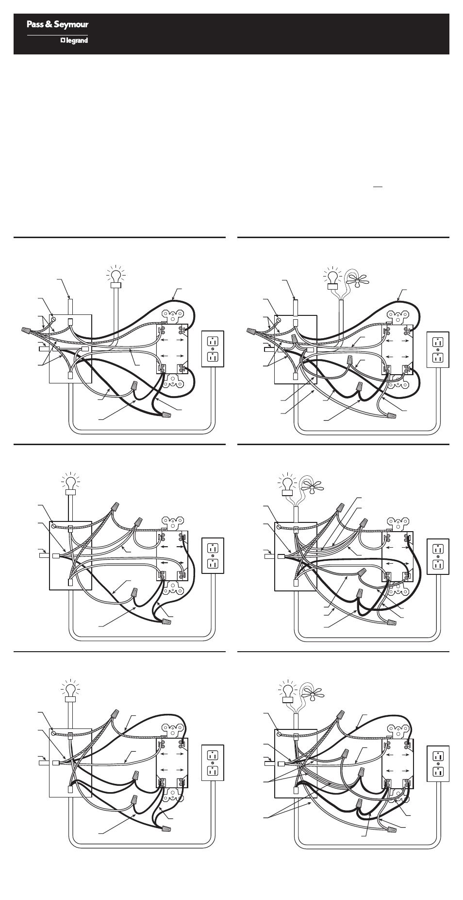
LOAD CABLE BRINGS POWER TO OTHER RECEPTACLES (OPTIONAL)
SWITCHED LOAD
GROUND
GROUND
CONNECTION
TO BOX
LINE CABLE
BRINGS POWER
TO THE SWITCH
FROM CIRCUIT
BREAKER #2
ELECTRICAL
BOX
LINE CABLE BRINGS
POWER TO THE GFCI FROM
CIRCUIT BREAKER #1
WHITE
BLACK
SWITCH
LEAD
BLACK
SWITCH
LEAD
GROUND
HOT
BLACK
LINE
LOAD
W
HI
TE
HO
T
W
HI
TE
HO
T
Wiring Diagram A1
(Single Switch Cat. #1595SWT)
LINE CABLE BRINGS
POWER TO THE GFCI FROM
CIRCUIT BREAKER #1
LOAD CABLE BRINGS POWER TO OTHER RECEPTACLES (OPTIONAL)
GROUND
GROUND
CONNECTION
TO BOX
LINE CABLE
BRINGS POWER
TO THE SWITCH(ES)
FROM CIRCUIT
BREAKER #2
ELECTRICAL
BOX
WHITE
YELLOW
SWITCH
LEAD
BLACK
COMMON
SWITCH
LEAD
GROUND
HOT
BLACK
RED
SWITCH
LEAD
HOT
LIGHT
HOT
FAN
SWITCHED LOADS
FAN
LIGHT
LINE
LOAD
W
H
IT
E
H
O
T
W
H
IT
E
H
O
T
Wiring Diagram A2
(Double Switch Cat. #15952SWT)
LOAD CABLE BRINGS POWER TO OTHER RECEPTACLES (OPTIONAL)
SWITCHED LOAD
GROUND
GROUND
CONNECTION
TO BOX
LINE CABLE
BRINGS POWER
TO THE GFCI
AND SWITCH
ELECTRICAL
BOX
WHITE
BLACK
SWITCH
LEAD
BLACK
SWITCH
LEAD
BLACK
LINE
LOAD
W
HI
TE
HO
T
W
HI
TE
HO
T
Wiring Diagram B1
(Single Switch Cat. #1595SWT)
LOAD CABLE BRINGS POWER TO OTHER RECEPTACLES (OPTIONAL)
SWITCHED LOAD
GROUND
GROUND
CONNECTION
TO BOX
LINE CABLE
BRINGS POWER
TO THE GFCI
ELECTRICAL
BOX
WHITE
BLACK
SWITCH
LEAD
BLACK
SWITCH
LEAD
BLACK
LINE
LOAD
W
HI
TE
HO
T
W
HI
TE
HO
T
Wiring Diagram C1
(Single Switch Cat. #1595SWT)
LOAD CABLE BRINGS POWER TO OTHER RECEPTACLES (OPTIONAL)
GROUND
GROUND
CONNECTION
TO BOX
LINE CABLE
BRINGS POWER
TO THE GFCI
AND SWITCHES
ELECTRICAL
BOX
BLACK
COMMON
SWITCH
LEAD
YELLOW
SWITCH LEAD
RED
SWITCH LEAD
LIGHT
FAN
SWITCHED LOADS
FAN
LIGHT
LINE
LOAD
W
H
IT
E
H
O
T
W
H
IT
E
H
O
T
FAN LEAD
LIGHT LEAD
WHITE
Wiring Diagram B2
(Double Switch Cat. #15952SWT)
LOAD CABLE BRINGS POWER TO OTHER RECEPTACLES (OPTIONAL)
GROUND
GROUND
CONNECTION
TO BOX
LINE CABLE
BRINGS POWER
TO THE GFCI
ELECTRICAL
BOX
WHITE
YELLOW
SWITCH LEAD
BLACK
BLACK
COMMON
SWITCH LEAD
RED
SWITCH LEAD
SWITCHED LOADS
FAN
LIGHT
LINE
LOAD
W
H
IT
E
H
O
T
W
H
IT
E
H
O
T
FAN LEAD
LIGHT LEAD
Wiring Diagram C2
(Double Switch Cat. #15952SWT)