Legrand 1594CMA User Manual
Installation and operating instructions, Instructions dʼinstallation et dʼutilisation, Portable ground fault circuit interrupter (gfci)
GENERAL
Pass & Seymour/Legrandʼs portable ground fault circuit interrupter (GFCI) provides personnel ground fault protection. Conventional
over-current protection devices such as fuses and circuit breakers cannot protect people from electrical shock. Those devices are
designed to disconnect the power when currents of several amperes flow from the hot wire to ground. However, currents as low as
a few milliamperes can be dangerous to normal healthy human beings. One ampere equals 1000 milliamperes.
Many electrical shocks occur when the path of current flow is from the hot wire through the metal housing of a defective tool or
appliance, through the body of a human being to ground. Because of the resistance of the human body to electrical current flow,
the current will be quite low relative to that required to cause conventional over-current protection devices to function. However,
it is likely to be high enough to cause a painful or possibly lethal electric shock to a human being.
Pass & Seymour/Legrandʼs portable GFCI is designed to remove power from the equipment loads when these loads have a
potentially lethal ground current in excess of six milliamperes. Normal loads will draw current from the Hot Conductor (black wire)
and return it to the power source through the Neutral Conductor (white wire). Faulty loads can return some of the current to the
power source through a ground path such as a water pipe, gas pipe, wet floor, third conductor (green wire), or worst of all, through
a person who is in contact with an extrinsic ground.
The Pass & Seymour/Legrand portable GFCIʼs rugged construction allows it to be used in outdoor or indoor locations, where
ground fault protection is desired. When energized by actuation of the reset button, it will conveniently supply power to any power
tool or appliance whose load requirement does not exceed rated voltage and currents.
WARNING
These models are rainproof user attachable line cord auto reset GFCIs. The electronic compartments of these units have been
sealed. Do not loosen or remove any of the four screws holding the cover in place.
CORD SELECTION
The type and size of cord usable with these products are:
SJT, SJTW – AWG 18, 2 Conductor through AWG 12, 3 Conductor.
NOTE: The cord diameter should be in the range of 5/16 to 5/8 inch to fit the wire clamp.
WARNING
It is most important to use the correct size wire for the application. A fire hazard could exist due to under-sized current carrying
capacity. If the GFCI is being connected to an appliance whose power cord was installed by the appliance manufacturer, it is
assumed the correct connectors and wire have been used, and they can be connected to both input and output of the GFCI. If the
cord is for general use, as in an extension cord, then the wire size used must be at least No. 14 AWG for 15 amp rating.
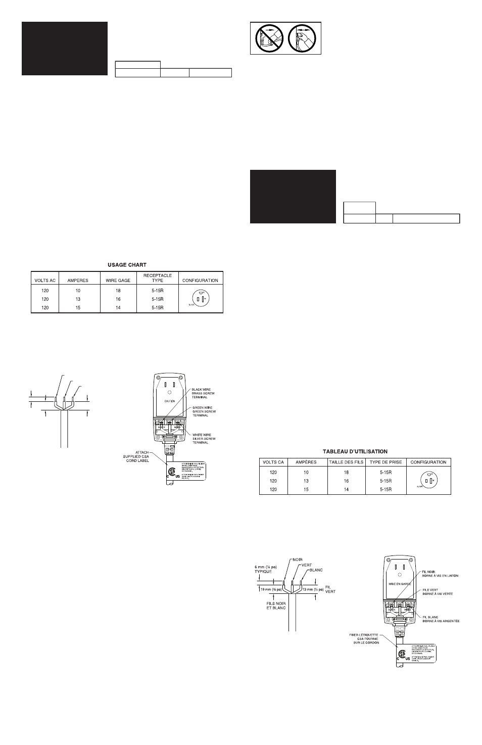
The chart below is a list of cord sizes and connectors usable with these products.
NOTE: If cord length longer than 50 ft is used, increase the wire gage to the next size, i.e., 13 AMP with over 50 ft of power cord –
use 14 AWG; 15 AMP, with over 50 ft of power cord – use 12 AWG.
WIRING INSTRUCTIONS
1. Remove strain relief cover. Mark wire and carefully prepare as noted in Fig. 1. Slide cable seal grommet(s) over cable jacket
before attaching wires to terminals. Orient as shown in Fig. 2.
2. IMPORTANT: Wires must be connected to the correct terminals; otherwise an electric shock hazard may exist. Attachment is
made by first loosening the terminal screws so adequate space is provided in the terminal opening. Then connect the black
wire to the terminal marked black. Connect the white wire to the terminal marked white. Connect the green wire to the center
(green) terminal. (*) Fully insert the wires in the appropriate terminal opening and tighten the terminal screws securely.
WARNING. DO NOT capture the conductor insulation, and also make sure that no loose strands of wire protrude outside the
terminal area which could contact strands from the other conductors. (See Fig. 2 and Fig. 3)
3. After connecting the wire per Para. 2, locate the strain relief clamp over the two screw holes inside the cable entry area (over
the cord jacket), and secure using the two larger screws. While alternating between the screws, gradually tighten the clamp
while holding the outer jacket of the wire fully under the clamp until it is tightened securely. After tightening the clamp, position
the strain relief cover over the four holes and cord jacket, position the cord jacket carefully and tighten securely using the four
smaller screws.
OPERATING INSTRUCTIONS
1. Connect the power cord to the GFCI in accordance with the WIRING INSTRUCTIONS.
2. Plug unit into a 120 VAC socket.
3. Verify that the light between the Test and the Reset Button is illuminated. (Note: This denotes that output power is available.)
4. Press the Test Button.
5. Verify that the light between the Test and the Reset Button is not illuminated.
6. Press and release the Reset Button.
7. Verify that the light between the Test and Reset Button is illuminated.
WARNING
1. If the GFCI fails to trip when the Test Button is pressed, or fails to reset, the device may be defective and should be returned to
Pass & Seymour for examination.
2. If the GFCI tests properly with only the input power cord attached, but trips each time the output appliance cord is connected,
then the appliance probably has a ground fault and needs to be repaired or replaced. DO NOT BYPASS THE GFCI IF THIS
CONDITION OCCURS. A REAL SHOCK HAZARD MAY EXIST.
IMPORTANT NOTE:
The Pass & Seymour Portable GFCI will provide protection against ground faults when used with a 2-wire outlet receptacle and a
3-wire to 2-wire adapter. It is always desireable, where possible, to use a 3-wire grounded receptacle because a ground provides
additional protection against electrical shock hazard. The adapter should be of the type that can be grounded to the outer
mounting plate screw.
The Pass & Seymour Portable GFCI does not sense ground faults in the input conductors. Therefore, it is always recommended
that if any extension cords are used, they should be connected between the GFCIʼs output and the tool or appliance to be
powered.
CAUTION
1. In order to avoid the possibility of nuisance tripping, do not connect any electrical cord longer then 250 feet to the GFCI output.
2. This device is to be used on normal 120V, 60Hz electrical distribution systems ONLY.
3. Ground fault circuit interrupters, whether Pass & Seymour or any other, do not protect against electrical shock due to contact
with both power conductors, and also due to a fault in any wiring supplying the device.
4. Test frequently and before each use to ensure correct operation.
5. The GFCI is designed as a protective device. DO NOT use as an off/on switch.
LIMITED ONE YEAR WARRANTY
Pass & Seymour/Legrand will remedy any defect in workmanship or material in Pass & Seymour/Legrand products which may
develop under proper and normal use within one year from the date of purchase by a consumer. (1) by repair or replacement, or at
Pass & Seymour/Legrandʼs option, (2) by return of the amount equal to the consumerʼs purchase price. Such remedy is IN LIEU
OF ANY AND ALL EXPRESSED OR IMPLIED WARRANTIES OF MERCHANTABILITY OR FITNESS FOR A PARTICULAR
PURPOSE. Such remedy by Pass & Seymour/Legrand does not include or cover cost of labor for removal or reinstallation of the
product. ALL OTHER FURTHER ELEMENTS OF DAMAGE (INCIDENTAL OR CONSEQUENTIAL DAMAGES) FOR BREACH
OF ANY AND ALL EXPRESSED OR IMPLIED WARRANTIES INCLUDING WARRANTIES OF MERCHANTABILITY OR
FITNESS FOR A PARTICULAR PURPOSE ARE EXCLUDED HEREBY. (Some states do not allow disclaimer or exclusion or
limitation of incidental or consequential damages, so the above disclaimers and limitation or exclusion may not apply to you.) ANY
IMPLIED WARRANTIES INCLUDING WHERE REQUIRED WARRANTIES OF MERCHANTABILITY OR FITNESS FOR A
PARTICULAR PURPOSE SHALL BE LIMITED TO THE ONE YEAR PERIOD SET FORTH ABOVE. (Some states do not allow
limitation on how long an implied warranty lasts, so the above limitation may not apply to you.)
To ensure safety, all repairs to Pass & Seymour/Legrand products must be made by Pass & Seymour/Legrand or under its specific
direction. Procedure to obtain performance of any warranty obligation is as follows: (1) Contact Pass & Seymour/Legrand, P.O.
Box 4822, Syracuse, NY 13221 for instructions concerning return or repair; (2) return the product to Pass & Seymour/Legrand,
postage paid, with your name and address and a written description of the installation or use of the Pass & Seymour/Legrand
product, and the observed defects or failure to operate, or other claimed basis for dissatisfaction.
This warranty gives you specific legal rights and you may also have other rights which vary from state to state.
NOTE:
Remove from receptacle by grasping the body of the GFCI.
Not the cord.
¼”
TYP.
BLACK
& WHITE
WIRES
GREEN
WIRES
BLACK
GREEN
WHITE
¾”
½”
FIG. 1
FIG. 2
Right Angle Models
(*) If there is no green wire in the cord, leave the green terminal
unconnected. WARNING: The green terminal is for GROUND ONLY.
Connecting power conductors to the ground terminal would pose a
serious shock hazard.
After installing the leads to the terminals, install clamp and covers
per instructions.
GÉNÉRALITÉS
Le disjoncteur de fuite à la terre (DDFT) portable Pass & Seymour/Legrand protège les utilisateurs contre les défauts de terre. Les
dispositifs traditionnels de protection contre les surtensions, tels que les fusibles et les disjoncteurs ordinaires, ne protègent pas
des chocs électriques. Ces dispositifs sont conçus pour couper lʼalimentation lorsquʼun courant de plusieurs ampères sʼétablit entre
le fil chargé (la phase) et la terre. Cependant, des courants ne mesurant que quelques milliampères peuvent être dangereux pour
un utilisateur normal en bonne santé. Un ampère est égal à 1000 milliampères.
De nombreux chocs électriques sont dus au passage dʼun courant électrique entre le fil chargé et le corps de lʼutilisateur relié à
la terre par lʼintermédiaire du boîtier métallique dʼun outil ou dʼun appareil ménager en mauvais état. Du fait de la résistance du
corps humain au passage des courants électriques, le courant sera relativement faible par rapport à celui qui est nécessaire pour
déclencher les dispositifs traditionnels de protection contre les surtensions. Cependant, ce courant sera probablement suffisant
pour causer un choc électrique douloureux, voire mortel.
Le DDFT portable Pass & Seymour/Legrand est conçu pour déconnecter lʼalimentation électrique de lʼéquipement lorsquʼil existe
un courant de terre potentiellement mortel de plus de six milliampères. Un équipement normal soutire le courant du conducteur
chargé (fil noir) et le renvoie à la source dʼalimentation par le neutre (fil blanc). Certains équipements défectueux peuvent renvoyer
une partie du courant à la source dʼalimentation par une boucle de terre telle quʼun tuyau dʼeau ou de gaz,
un sol humide, un troisième conducteur (fil vert) ou, dans le pire des cas, par lʼutilisateur qui est en contact avec une terre
extrinsèque.
La construction robuste du DDFT portable Pass & Seymour/Legrand permet de lʼutiliser à lʼintérieur comme à lʼextérieur, là
où il est souhaitable dʼassurer une protection contre les défauts de terre. Une fois quʼil a été mis sous tension en appuyant
sur le bouton de réarmement, il permet dʼalimenter nʼimporte quel outil ou appareil ménager ne dépassant pas la tension et le
courant nominaux.
AVERTISSEMENT
Ces modèles sont des DDFT étanches à réenclenchement automatique installables par lʼutilisateur sur un cordon dʼalimentation.
Les composants électroniques de ces unités sont scellés. Ne desserrer ou retirer aucune des quatre vis maintenant le couvercle
en position.
CHOIX DU CORDON
Les types et dimensions de cordon utilisables avec ces produits sont les suivants :
SJT, SJTW – AWG 18, 2 conducteurs à AWG 12, 3 conducteurs.
REMARQUE : Le diamètre du cordon doit être compris entre 7,9 et 15,9 mm (5/16 et 5/8 po) pour être compatible avec le collier
de fixation.
AVERTISSEMENT
Il est très important dʼutiliser des fils du bon diamètre pour lʼapplication considérée. Un danger dʼincendie peut exister si le cordon
est sous-dimensionné. Si le DDFT est connecté à un appareil dont le cordon a été installé par le fabricant de lʼappareil, il peut être
supposé que les bons connecteurs et le bon cordon ont été utilisés et quʼils peuvent être connectés à lʼentrée et à la sortie du
DDFT. Si le cordon est destiné à une utilisation générale, comme une rallonge électrique, les fils doivent être dʼau moins 14 AWG
(15 ampères).
Le tableau ci-dessous indique les connecteurs et cordons utilisables avec ces produits.
REMARQUE : Si le cordon mesure plus de 15 m (50 pi) de long, utiliser un cordon de la taille immédiatement supérieure. Par
exemple: 13 A, avec un cordon de plus de 15 m (50 pi) – utiliser 14 AWG; 15 A, avec un cordon de plus de 15 m (50 pi) – utiliser
12 AWG.
INSTRUCTIONS DE CÂBLAGE
1. Retirer le couvercle de réduction de tension. Marquer les fils et préparer soigneusement comme indiqué à la Fig. 1. Enfiler le
ou les passe-fils sur la gaine du câble avant de fixer les fils aux bornes. Orienter comme illustré à la Fig. 2.
2. IMPORTANT : Les fils doivent être connectés aux bornes correctes pour éviter tout danger de choc électrique. Desserrer tout
dʼabord les vis des bornes pour que la borne sʼouvre suffisamment. Connecter ensuite le fil noir à la borne « Black ».
Connecter le fil blanc à la borne « White ». Connecter le fil vert à la borne centrale verte. (*) Insérer les fils bien à fond dans la
borne correcte et bien serrer les vis des bornes. AVERTISSEMENT. NE PAS insérer lʼisolation du fil. De plus, sʼassurer
quʼaucun brin des fils ne dépasse des bornes car il pourrait entrer en contact avec dʼautres fils et créer un court-circuit. (Voir
Fig. 2 et Fig. 3.)
3. Après avoir connecté les fils selon les instructions du paragraphe 2, placer le collier de réduction de tension au-dessus des
deux trous de vis à lʼintérieur de la zone dʼentrée du câble (au-dessus de la gaine du cordon) et fixer avec les deux grosses vis.
Tout en alternant entre les deux vis, serrer le collier graduellement tout en maintenant la gaine extérieure entièrement enfoncée
sous le collier. Serrer jusquʼà ce que la gaine soit solidement fixée. Après avoir serré le collier, placer le couvercle de réduction
de tension au-dessus des quatre trous et de la gaine du cordon, placer la gaine du cordon avec soin et bien serrer les quatre
petites vis.
FIG. 1
FIG. 2
Modèles à angle droit
(*) Sʼil nʼy a pas de fil vert dans le cordon, ne pas connecter
la borne verte. AVERTISSEMENT : La borne verte est
destinée à la TERRE UNIQUEMENT. La connexion dʼun
conducteur dʼalimentation à la borne de mise à la terre
peut créer un danger de choc électrique sérieux.
Après avoir fixé les fils aux bornes, installer le collier
et les couvercles selon les instructions.
INSTRUCTIONS
DʼINSTALLATION ET
DʼUTILISATION
DISJONCTEUR
DE FUITE À LA TERRE
PORTABLE (DDFT)
INSTALLATION AND
OPERATING
INSTRUCTIONS
PORTABLE
GROUND FAULT CIRCUIT
INTERRUPTER (GFCI)
MODEL NUMBER
1594-CMA
15 Amp
AUTO-RESET
NUMÉRO
DE MODÈLE
1594-CMA
15 Amp RÉARMEMENT AUTOMATIQUE