Legrand DR1103PV User Manual
Trademaster, Decorator rotary dimmer, Atenuador giratorio decorativo
R E A D
A N D
S A V E
T H E S E
I N S T R U C T I O N S
To be installed by a certified electrician or other qualified person.
WARNING – To prevent severe shock or electrocution, always turn power off at the service
panel before installing this unit, working on the circuit, or changing a lamp.
CAUTION – To reduce the risk of overheating and possible damage to other equipment, do
not install incandescent dimmer to control a receptacle, a fluorescent light or bulb, a
motor-operated appliance, or a transformer-supplied appliance.
Do not use dimmer with incandescent lamps whose power requirements exceeds maxi-
mum power (stated in Watts) of the dimmer.
Do not connect dimmer to power source other than 120VAC, 60 Hz only.
A 50W minimum load is required.
Use copper wire only.
DIRECTIONS
1. Disconnect power to circuit by removing fuse or turning circuit breakers to OFF
before installing.
2. Remove existing wall plate and switch mounting screws.
3. Disconnect existing switch from circuit. 3-way installation: Identify the “Common” wire
(wire connected to the terminal marked common or odd colored terminal). For “new”
installation identify wire connected to power source or to the load.
4. Strip existing wires using gauge on back of device.
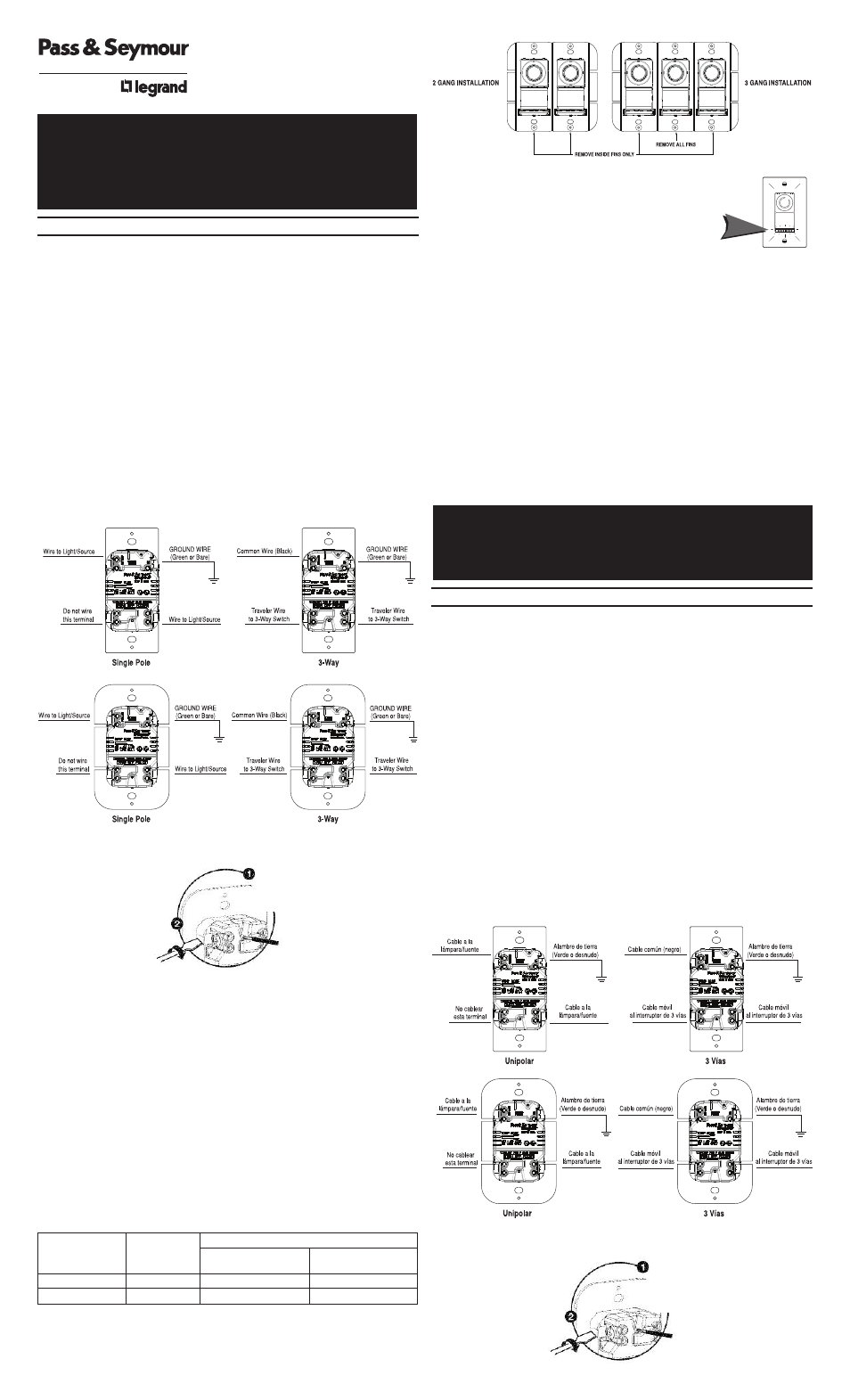
5. Connect dimmer as shown in the wiring and installation diagrams.
INSTALLATION DIAGRAMS FOR DIMMERS
6. Install dimmer in wall box, with word ‘TOP’ on metal strap right side up, using
mounting screws provided.
7. Attach wall plate.
8. Restore power and follow operating instructions.
Note: Protect from dirt and dust. The dimmer can be damaged from contaminates
encountered during the construction process. If lighting is required prior to the construction
process completion, then a switch should be temporarily installed in place of the dimmer.
The dimmer should not be installed until the construction process is complete.
OPERATING INSTRUCTIONS:
1. Toggle the switch provided to turn the dimmer ON and OFF.
2. To change lighting level rotate the knob clockwise or counterclockwise until desired
level is reached.
NOTE: Only a three way switch can be used to operate the light from a second location.
Control may feel warm to the touch in normal operation. This control is intended for
installation in a U.L. Listed metal or (polymeric) plastic outlet box.
MULTIPLE GANGING OF DIMMERS & OTHER DEVICES
Any combination of dimmer models and other devices may be ganged together. Break
off tabs are provided on the 1100W dimmer straps for multi-gang applications. Pry off
the tabs using pliers before installation, as shown in the multi-gang illustration. De-rate
the maximum load according to the following table:
Light Module: (sold separately, Catalog # TM8LMCC)
Transform in minutes a standard dimmer into an illuminated dimmer (ON
when light is OFF) – allows the dimmer to be found in the dark.
Average 20-year life expectancy.
No wiring – quick snap-in installation.
Any dimmer damage due to improper installation is not covered under warranty.
LIFETIME WARRANTY
The device you have purchased is warranted under normal use against defects in workmanship and
materials for as long as you own the device. If the device fails due to manufacturing defect during
normal use, return the device for replacement to the store where purchased or send to: Pass &
Seymour Legrand, 50 Boyd Avenue, Syracuse, NY 13209. All requests for replacement must include a
dated sales receipt (legible copies acceptable). ALL OTHER WARRANTIES, INCLUDING BUT NOT
LIMITED TO ANY WARRANTIES OF MERCHANTABILITY OR FITNESS FOR A PARTICULAR PURPOSE,
ARE LIMITED TO A PERIOD OF TWO YEARS FROM THE DATE OF PURCHASE. YOUR SOLE AND
EXCLUSIVE REMEDY AGAINST PASS & SEYMOUR LEGRAND UNDER ANY WARRANTY SHALL BE THE
EQUIVALENT REPLACEMENT OF THE DEVICE. IN NO EVENT SHALL ANY WARRANTY APPLY TO ANY
DEFECT ARISING OUT OF ANY ALTERATION OF THE DEVICE, IMPROPER WIRING, IMPROPER
INSTALLATION, MISUSE, ABNORMAL USE OR NEGLIGENCE. IN NO EVENT SHALL PASS & SEYMOUR
LEGRAND BE LIABLE FOR LOST PROFITS, INDIRECT, SPECIAL, EXEMPLARY, INCIDENTAL OR
CONSEQUENTIAL DAMAGES. Some states do not allow limitations on how long implied warranties
last and do not allow exclusion or limitation of incidental or consequential damages. Some of the
above limitations or exclusions may not apply to every purchaser.
INSTRUCCIONES EN ESPAÑOL
L E A
Y
G U A R D E
E S T A S
I N S T R U C C I O N E S
Para ser instalado por electricista certificado u otra persona capacitada.
ADVERTENCIA: Para prevenir una sacudida eléctrica severa o electrocución, siempre
CORTE la electricidad en el panel de servicio antes de instalar esta unidad, trabajar en
el circuito, o cambiar una lámpara.
AVISO: Para evitar el recalentamiento y los posibles daños a otro equipo, no instale este
dispositivo para controlar un tomacorriente, una lámpara o tubo fluorescente, un elec-
trodoméstico a motor o un electrodoméstico alimentado por un transformador.
No use el reductor de luz con lámparas incandescentes cuyas requisitos de potencia
exija la potencia máxima (indicada en Wats) del reductor de luz.
No conecte al reductor de luz a otra fuente de potencia que no sea solo 120VAC, 60Hz.
Una carga mínima de 50W es requerida.
Solo utilice cables de cobre.
INSTRUCCIONES:
1. Desconecte la corriente del circuito quitando el fusible o APAGANDO los disyuntores
antes de instalar.
2. Quite la placa existente y los tornillos de la pared y quite el interruptor.
3. Desconecte del circuito el interruptor existente. Instalación de 3 vías: Identifique el
alambre “Común” (alambre conectado a la terminal marcado ‘common/común’ o al
terminal de color distinto). Para instalación “nueva”, identifique el alambre
conectado al suministro eléctrico o a la carga.
4. Pele el alambre utilizando la guía en la parte trasera del aparato.
5. Conecte el reductor de luz como mostrado en el diagrama de instalación y alambrado.
DIAGRAMA DE INSTALACION
NEW
INSTALLATION INSTRUCTIONS
TradeMaster
®
DECORATOR ROTARY DIMMER
P/N 340875
00
INSTRUCCIONES DE INSTALACÓN
TradeMaster
®
ATENUADOR GIRATORIO DECORATIVO
Screw Pressure Plate Back Wire
Securely tighten
screw beneath
wire hole to retain
inserted wire.
Insert wire
to bottom
of hole.
Termination takes
#12 or #14 AWG
stranded or solid,
copper conductors.
MULTI-GANG DE-RATING
DIMMER
MAXIMUM
2 GANG
3 GANG
CATALOG #
LOAD
INSTALLATION
INSTALLATION
DR1103-P_V
1100W
900W
800W
DR703-P_V
700W
700W
700W
Atornille el Alambre Trasero de la Tapa Presora
Apriete el tornillo
debajo del hueco del
alambre para aguantar
el alambre insertado.
Introduzca el alambre al
hueco del fondo.
La terminación acepta
conductores trenzados
o sólidos #12 o #14 AWG
de cobre.