Legrand CDADAPTORKITBK User Manual
Titan, Commercial products adaptor kit, Installation instructions
This product allows for P&S switches, P&S receptacles, P&S GFCIs, and P&S Commercial Network
Wiring Keystone products to be multi-ganged with Titan™ Commercial Dimmers.
PACKAGE CONTENTS / CONTENIDO DEL PAQUETE / CONTENU DU PAQUET
Adaptor Kit Assembly
Coupler
Small Coupler
Screws for Fastening Device to Sub-plate
Juego de adaptador
Acoplador Acoplador pequeño
Tornillos para afianzar el ensamble a la placa de base
Ensemble adaptateur
Coupleur
Petit coupleur
Vis pour fixation de l'ensemble sur la plaque de base
IMPORTANT NOTES: Read the following before installation:
WARNING – To prevent severe shock or electrocution, always turn power OFF at the service panel before
installing this device, working on the circuit, or changing a lamp.
• To be installed by a certified electrician or other qualified person.
• Cleaning Instructions: Wipe with a damp, clean cloth. DO NOT clean with chemicals or cleaning solutions.
WALL PLATE LABELING SYSTEM
These wall plates contain a label holding slot. A 0.33" x 1.5" label can be placed in this
label holding slot. These labels can be printed from an Avery
®
standard template:
Divider tab inserts 8-Tabs or equivalent.
Install the label with the following procedure:
1. Disconnect power to the circuit by removing fuse
or turning circuit breakers OFF.
2. Remove the wall plate by placing a small flat head
screwdriver into one of the four slots located at the
top and bottom of the wall plate. Gently twist a half
turn until the plate pops off.
3. Slide the label in from the back side of the wall plate
(as shown at right).
SINGLE GANG INSTALLATION INSTRUCTIONS
1. Disconnect power to circuit by removing fuse or turn circuit breakers OFF
before installing.
2. Remove (unsnap) wall plate from the Adaptor Kit Assembly.
3. Remove plaster ears from the device. Break off with pliers (Figure 1).
Time saving tip: P&S devices may be ordered without the plaster ears through
P&S Configurable Solutions. Please consult the catalog for more information.
4. Attach the device to the sub-plate with the two screws
provided (see Figure 2).
5. Wire the device per the manufacturers instructions and
install the assembly in a single gang wall box with the
screws provided (see Figure 2).
6. Insert the label, attach the wall plate and restore power
to the circuit.
Figure 1 / Figura 1 / Figure 1
TITAN
™
COMMERCIAL PRODUCTS ADAPTOR KIT
INSTALLATION INSTRUCTIONS
P/N 340847 Rev. B
Figure 2 / Figura 2 / Figure 2
Device with plaster ears removed / Dispositivo sin los rebordes de masilla / Dispositif sans les extrémités arrondies
Screws for fastening the device
to the sub-plate (supplied)
Tornillos para afianzar el dispositivo
a la placa de base (incluidos)
Vis pour fixer le dispositif à la
plaque de base (fournies)
Wall plate
Placa de pared
Plaque murale
End caps
Tapas laterales
Extrémités latérales
Sub-plate / Placa de base / Plaque de base
Screws for fastening the device assembly to wall box (supplied)
Tornillos para afianzar el dispositivo a la caja de pared (incluidos)
Vis pour fixer le dispositif à la plaque murale (fournies)
Screws for Fastening Device Assembly to Wall-box
Tornillos para afianzar el ensamble a la caja de pared
Vis pour fixation de l'ensemble sur la boîte murale
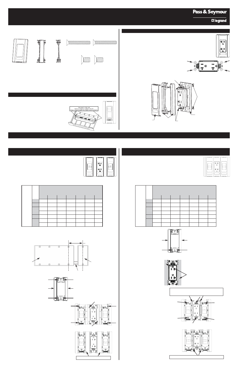
MULTI GANG INSTALLATION INSTRUCTIONS
FINS ARE NOT REMOVED
Note: A 3-gang installation of two Narrow Dimmers and an Adaptor
Kit is shown and described below.
Any Combination of Wide Dimmers and Narrow Dimmers/Adaptor
Kits will gang the same way.
1. Select the correct box size from Table 1.
Table 1 – Wall-Box Gang Requirements –
FINS are NOT REMOVED
Tabla 1 – Requerimientos para instalación en grupo en caja de pared – Las ALETAS NO SE HAN RETIRADO
Tableau 1 – Exigences de groupement dans les boîtes murales – Les ailettes NE SONT PAS retirées
*Wall-box requirements for ganging an even number of narrow dimmers/adaptor kits.
*Requerimientos de caja de pared para instalación de una cantidad par de atenuadores angostos / juegos de adaptadores.
*Exigences pour groupement d'un nombre pair de gradateurs étroits / ensembles adaptateurs.
4+1 set up shown below:
La instalación 4+1 se muestra a continuación:
Cas 4+1 illustré ci-dessous :
2. Remove the wall plate (unsnap) and remove the end
cap between adjacent devices (2 screws for each end
cap). Keep these screws as they will be needed at
step #5. (See Figure 3.)
Note: The end cap that is not between the devices does
not get removed.
3. Remove the plaster ears from the device (see Figure
1) and attach the device to the sub-plate, with the
screws provided. (See Figure 2).
4. Wire the device per the manufacturer’s instructions
and install the devices in the wall box using the
mounting screws provided (leave mounting screws
“finger tight” at this point). (See Figure 4.)
5. Attach the couplers between the devices with the
screws that were removed in step 2. (See Figure 5.)
6. Tighten the mounting screws, insert the label, attach
the wall plate, and restore power to the circuit.
MULTIPLE GANGING OF ADAPTOR KITS AND TITAN
™
DIMMERS
This Adaptor Kit will allow for any combination of Titan™ Dimmers and P&S wiring devices to be ganged together. Using a vise or heavy-duty pliers, remove the fins on
either or both sides of the heat sink, or sub-plate as necessary. See Table 1 and Table 2 for proper selection and placement of outlet boxes.
Chase nipple / Tubo de conexión / Manchon de raccordement
4-gang wall box
Caja de pared cuádruple
Boîte murale quadruple
1-gang wall box
Caja de pared sencilla
Boîte murale simple
2.712
Narrow Dimmers/Adaptor Kits
Adaptadores angostos / Juegos de adaptadores
Gradateurs étroits / Ensembles adaptateurs
0
1
2
3
4
5
6
0
0
1
1+1*
4
4+1*
7
7+1*
1
1
3
5
6
8
9
11
2
4
5
7
8
10
11
13
3
6
8
9
11
12
14
15
4
9
10
12
13
15
16
-
5
11
13
14
16
–
–
-
6
14
15
–
–
–
–
Wide Dimmer
s
Atenuador
es anchos
Gr
adateur
s lar
ges
MULTI GANG INSTALLATION INSTRUCTIONS
FINS ARE REMOVED
Note: A 3-gang installation of two Narrow Dimmers and an Adaptor Kit is
shown and described below.
Any Combination of Wide Dimmers and Narrow Dimmers/Adaptor Kits
will gang the same way.
1. Select the correct box size from Table 2.
Table 2 – Wall-Box Gang Requirements – FINS are REMOVED
Tabla 2 – Requerimientos para instalación en grupo en caja de pared – Las ALETAS se han QUITADO
Tableau 2 – Exigences de groupement dans les boîtes murales – Les ailettes SONT retirées
2. Remove the wall plate (unsnap)
and remove the end cap between
adjacent devices (2 screws for each
end cap). Keep these screws as
they will be needed at step #6. (See
Figure 6.)
Note: The end cap that is not between
the devices does not get removed.
3. Remove the plaster ears from the
device (see Figure 1) and attach the
device to the sub-plate, with the
screws provided. (See Figure 2).
4. Remove the fins between adjacent
devices. (See Figure 7.)
5. Wire the device per the manu-
facturer’s instructions and install
the devices in the wall box using
the mounting screws provided
(leave mounting screws “finger
tight” at this point). (See Figure 8.)
6. Attach the small couplers between
the devices with the screws that
were removed in step 2. (See
Figure 9.)
7. Tighten the mounting screws,
insert the label, attach the wall
plate, and restore power to the
circuit.
Remove fins between adjacent devices using
a vise or heavy-duty pliers
Retire las aletas entre los dispositivos
adyacentes con una prensa de tornillo o
pinzas de servicio pesado
Retirer les ailettes entre les dispositifs
adjacents avec un étau ou de grosses pinces.
Small Couplers / Acopladores pequeños / Petits coupleurs
Remove this screw to remove End Cap
Retire este tornillo para retirar la tapa lateral
Retirer cette vis pour retirer l'extrémité latérale
End Cap
Tapa lateral
Extrémité latérale
Remove this screw to remove End Cap
Retire este tornillo para retirar la tapa lateral
Retirer cette vis pour retirer l'extrémité latérale
Remove this screw to remove End Cap
Retire este tornillo para retirar la tapa lateral
Retirer cette vis pour retirer l'extrémité latérale
End Cap
Tapa lateral
Extrémité latérale
Remove this screw to remove End Cap
Retire este tornillo para retirar la tapa lateral
Retirer cette vis pour retirer l'extrémité latérale
Fins are removed between adjacent devices
Las aletas se retiran de entre los dispositivos adyacentes
Les ailettes sont retirées entre les dispositifs adjacents
Figure 3
Figura 3
Figure 3
Remove this screw to remove End Cap
Retire este tornillo para retirar la tapa lateral
Retirer cette vis pour retirer l'extrémité latérale
End Cap
Tapa lateral
Extrémité latérale
Remove this screw to remove End Cap
Retire este tornillo para retirar la tapa lateral
Retirer cette vis pour retirer l'extrémité latérale
Remove this screw to remove End Cap
Retire este tornillo para retirar la tapa lateral
Retirer cette vis pour retirer l'extrémité latérale
End Cap
Tapa lateral
Extrémité latérale
Remove this screw to remove End Cap
Retire este tornillo para retirar la tapa lateral
Retirer cette vis pour retirer l'extrémité latérale
Figure 4 / Figura 4 / Figure 4
Figure 5 / Figura 5 / Figure 5
Figure 6 / Figura 6 / Figure 6
Figure 7 / Figura 7 / Figure 7
Figure 9 / Figura 9 / Figure 9
Figure 8 / Figura 8 / Figure 8
Couplers / Acopladores / Coupleurs
Narrow Dimmers/Adaptor Kits
Adaptadores angostos / Juegos de adaptadores
Gradateurs étroits / Ensembles adaptateurs
0
1
2
3
4
5
6
0
0
1
2
3
4
5
6
1
1
3
4
5
6
7
8
2
3
4
5
6
7
8
9
3
5
6
7
8
9
10
11
4
7
8
9
10
11
12
13
5
9
10
11
12
13
14
15
6
11
12
13
14
15
16
17
Wide Dimmer
s
Atenuador
es anchos
Gr
adateur
s lar
ges