Legrand 94812I User Manual
Fan speed & dual dimmer/ fan speed controls, Installation instructions
Toggle
To be installed by a certified electrician or other qualified person.
WARNING – To prevent severe shock or electrocution, always turn power OFF at the
service panel before installing this unit, working on the circuit, or changing a lamp.
CAUTION – To reduce the risk of overheating and possible damage to other
equipment, do not install to control a receptacle, a fluorescent light, or a
transformer-supplied appliance. Use this control only with fans that are marked
as suitable for use with solid-state fan speed controls.
Any number of fans may be controlled by a single fan speed control provided
the sum amperage rating of the fans does not exceed the amperage rating of
the fan control.
Do not connect fan control to power source other than 120VAC, 60 Hz only.
Use copper wire only.
FOR DUAL DIMMER/FAN SPEED CONTROL – It is necessary to add the
required third wire from the wall box switching location to the fan with the light
kit unit. This is because the fan and light kit are essentially two separate units.
CAUTION – The additional third wire required should not be confused with the
neutral wire, usually WHITE, nor the ground wire, normally GREEN, which
may already be routed through the wall box. Warranty is void when any of the
three wires are attached to the neutral wire or ground wire. This will cause a
direct short and damage the controlʼs circuitry beyond repair.
Use copper wire only.
DIRECTIONS
1. Disconnect power to circuit at the panel by removing fuse or turning circuit
breakers OFF before installing.
2. Remove wall plate and switch mounting screws, pull existing switch from
wall box.
3. Disconnect existing switch from circuit.
4. Connect fan speed control as shown in the installation diagram with wire
connectors provided.
5. Install speed control device in wall box, using mounting screws provided.
Restore power to the circuit.
6. If fan has a multi-speed switch, place switch in the MAXIMUM SPEED
position, then do not change the switch setting.
7. To adjust Anti-Stall feature (if equipped): Set the fan speed control to lowest
speed and turn the power off. To change the minimum speed, adjust the
trimpot through the access opening in the front of the fan speed control,
using a small, insulated, flat-tipped screwdriver.
8. Attach wall plate.
NOTE: A 0.5A minimum load is required. It is normal for the control to feel
warm during operation. Use a separate neutral wire for each phase of a
multiphase system containing a dimmer, and for high power single phase
applications where flickering is present.
INSTALLATION DIAGRAM FOR SPEED CONTROLS (wiring is same with
each of the fan speed control types)
Rotary
Slide
INSTALLATION DIAGRAM FOR DUAL DIMMER/FAN SPEED CONTROL
Identify fan/light kit wires. See fan/light
kit instructions (supplied by fan/light kit
manufacturer).
• Connect YELLOW wire from the
control
to
light
kit
lead
(incandescent only) with provided
wire connector.
• Connect RED wire from the control
to fan/motor lead with provided wire
connector.
• Connect BLACK wire from control to 120VAC hot wire with
provided wire connector.
• Connect GREEN (or uninsulated) wire from control to ground wire
or metal wall box with provided wire connector.
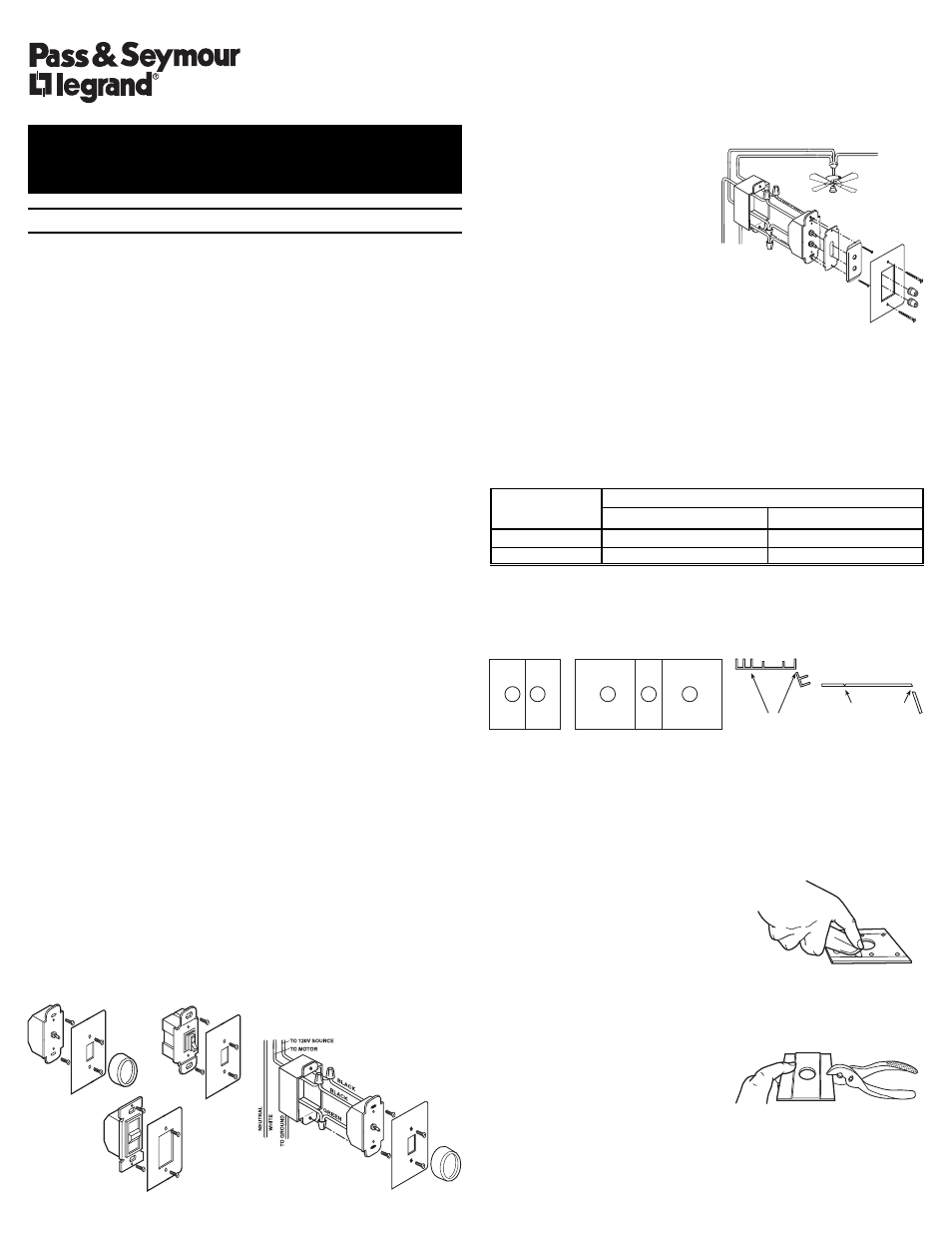
MULTIPLE GANGING OF CONTROLS
Any combination of fan control models may be ganged together. Using vise or
heavy-duty pliers, remove the outer fins on either or both sides, as necessary,
at the break-off points on the thin metal line at the base of the third fin. Fan
controls can be ganged without removing fins by proper selection and
placement of outlet boxes. When fins are removed, de-rate the maximum load
according to the following De-Rating Table:
MAXIMUM
FINS REMOVED
RATED LOAD
ONE SIDE
TWO SIDES
8 AMPS
7 AMPS
6 AMPS
12 AMPS
11 AMPS
10 AMPS
CAUTION : Sharp or jagged metal edges might be exposed where sections
were broken off. Use care when handling the control after this operation.
ILLUSTRATION FOR GANGING
HOW TO CUT PLASTIC FACEPLATE:
If fins are removed for ganging, the faceplate must be adjusted to match.
You may either score the groove on the back of the faceplate thoroughly with a
razor sharp packing knife, or you may partially score the groove, then
complete the break with pliers.
TO CUT THE FACEPLATE WITH KNIFE ONLY:
1. Lay faceplate face down on soft clean cloth,
on a flat solid surface to preserve finish.
2. Run knife vertically throughout groove
repeatedly until plastic separates.
3. Dress rough edges using very fine-grained
sand paper.
TO CUT THE FACEPLATE USING PLIERS AND KNIFE:
1. Lay faceplate face down on soft clean cloth, on a flat solid surface to
preserve finish.
2. Run knife vertically throughout groove
several times.
3. Hold faceplate firmly in one hand and
use pliers to bend the flat edge of the
fin away from the groove. Behind the
opposing ends first, then make a final
break at the middle, separating fin from
faceplate.
4. Dress rough edges using very fine-grained sand paper.
INSTALLATION INSTRUCTIONS
FAN SPEED & DUAL DIMMER/
FAN SPEED CONTROLS
R E A D A N D S A V E T H E S E I N S T R U C T I O N S !
Double-Gang
Mixed Combination-Gang
Fin Break-Off Points
ôtÉÉàñ
qÉprz
éts
wàêIQZaYî
prIèàíértR
qÉprz
Ñàêàé
ÉpÑâ
êàIátíêépÉ
ràÑÑàá
véàíás
véttá