Legrand HS1001 User Manual
Pir occupancy sensor, Installation & operating instructions
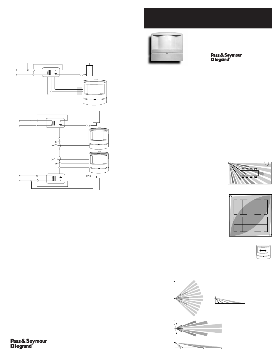
UNIT DESCRIPTION
The WA1001/HS1001 are 24VDC passive infrared (PIR) occupancy sensors
which control lighting or HVAC systems based on occupancy.
PIR sensing systems are passive systems which react to changes in infrared
energy (moving body heat) within the coverage area. PIR sensors must
directly “see” motion of an occupant to detect them, so careful consideration
must be given to sensor placement.
SPECIFICATIONS
Voltage . . . . . . . . . . . . . . . . . . . . . . . . . . . . . . . . . . 24VDC
Power Supply . . . . . . . . . . . Pass & Seymour Power Pack
Current Consumption . . . . . . . . . . . . . . . . . . . 8mA Typical
Time Adjustment . . . . . . . . . . . . . 15 seconds–30 minutes
Sensitivity Adjustment . . . . . . . . . . . . Minimum–Maximum
APPLICATION
Coverage may be slightly less than the maximum sensing distance depending
upon obstacles such as furniture or partitions. This must be considered
when planning the number of sensors and their placement. Also, total
coverage area will be smaller for lower mounting heights.
Enclosed office applications
The best location to install the WA1001 is in a
corner which does not face a door. Avoid placing
the sensor so that it can see out an open door
where it may be able to sense people walking by.
Also, avoid placing the sensor where obstacles
will block its view—the sensor must “see” the
occupants in order to detect them.
Conference Rooms, Large
Office Areas, and Classrooms
For these applications, the WA1001 is best. Place
sensor in the corner facing into the room. To
obtain maximum coverage in a partitioned work
area, use the sensors to create coverage zones
that overlap each other. As a general rule, you
should be able to view the sensor clearly from
each desk in the coverage area.
Aisleways, Hallways and Shelving Areas
In these types of applications, the HS1001 is used.
The HS1001 lens has a narrow, long-range view and should be
installed on a wall or ceiling at the end of an aisleway. It works
best when mounted at 10 ft.
COVERAGE PATTERNS
Coverages shown are maximum and represent coverage for half-step,
walking motion.
WIRING DIRECTIONS
WARNING – Turn power off at the circuit breaker before installing power pack
or sensors.
Note: Each power pack can supply power for up to eight sensors. If using
more than eight sensors, multiple power packs are required.
For normal installation, connect:
BLUE wire from power pack to BLUE wire from sensor.
RED wire from power pack to RED wire from sensor.
and BLACK wire from power pack to BLACK wire from sensor.
LIMITED FIVE YEAR WARRANTY
Pass & Seymour will remedy any defect in workmanship or material in Pass &
Seymour products which may develop under proper and normal use within
five (5) years from date of purchase by a consumer:
(1) by repair or replacement, or, at Pass & Seymour’s option, (2) by
return of an amount equal to consumer’s purchase price. Such remedy is
IN LIEU OF ANY AND ALL EXPRESSED OR IMPLIED WARRANTIES OF
MERCHANTABILITY OR FITNESS FOR A PARTICULAR PURPOSE. Such
remedy by Pass & Seymour does not include or cover cost of labor for
removal or reinstallation of the product. ALL OTHER FURTHER ELEMENTS
OF DAMAGE (INCIDENTAL OR CONSEQUENTIAL DAMAGES) FOR BREACH
OF ANY AND ALL EXPRESSED OR IMPLIED WARRANTIES INCLUDING
WARRANTIES OF MERCHANTABILITY OR FITNESS FOR A PARTICULAR
PURPOSE ARE EXCLUDED HEREBY. (Some states do not allow disclaimer or
exclusion or limitation of incidental or consequential damages, so the above
disclaimers and limitation or exclusion may not apply to you.) ANY IMPLIED
WARRANTIES INCLUDING WHERE REQUIRED WARRANTIES OF
MERCHANTABILITY OR FITNESS FOR A PARTICULAR PURPOSE SHALL BE
LIMITED TO THE FIVE YEAR PERIOD SET FORTH ABOVE. (Some states do
not allow limitations on how long an implied warranty lasts, so the above
limitation may not apply to you.)
To insure safety, all repair to Pass & Seymour products must be made by
Pass & Seymour, or under its specific direction. Procedure to obtain
performance of any warranty obligation is as follows: (1) Contact Pass &
Seymour, Syracuse, New York 13221, for instructions concerning return or
repair, (2) return the product to Pass & Seymour, postage paid, with your
name and address and a written description of the installation or use of the
Pass & Seymour product, and the observed defects or failure to operate, or
other claimed basis for dissatisfaction.
This warranty gives you specific legal rights and you may also have other
rights which vary from state to state.
US Patent No.:
4,787,722
INSTALLATION & OPERATING INSTRUCTIONS
WA1001/HS1001
PIR OCCUPANCY SENSOR
Part No. 340400 Rev. D
Printed in U.S.A.
P.O. Box 4822
Syracuse, NY 13221
(800) 223-4185
Control Output 24VDC
Common
+24VDC
Lighting
Load
White / Neutral
Red (Load)
Red (Line)
White
Black
Hot
Neutral
Power Pack
Re
d
Bl
ac
k
Bl
ue
Switch
Blue
Red
Black
Single Sensor Wiring
Blue (Control Output 24VDC)
Red (+24VDC)
White (Neutral)
Red (Load)
Red (Line)
White
Black
Hot
N
POWER PACK
Re
d
Bl
ac
k
Bl
ue
Switch
Black (Control Return)
Blue (Control Output 24VDC)
Red (+24VDC)
Lighting
Load
Lighting
Load
White (Neutral)
Red (Load)
Red (Line)
White
Black
Hot
N
POWER PACK
Re
d
Bl
ac
k
Bl
ue
Switch
Black (Control Return)
Multiple Sensors Wiring
Lens-plane
Dense Wide Angle Lens (WA1001)
up to 1200 sq ft
10ft
0
8ft
8ft
16ft
16ft
0
10 15ft
55ft
85 90ft
TOP
SIDE
Long Range Lens (HS1001)
up to 90 linear ft
33ft
0ft
1
TOP
SIDE
7ft
10ft
3
15ft
25ft
50ft
0