Legrand CSD1000LV User Manual
Pass & seymour
No: 340999 – 6/12 Rev. B
Pass & Seymour
®
360° Dual Technology • Line Voltage Occupancy Sensor with Light Level feature
Double technologie à 360° • Détecteur de présence sur secteur d’alimentation avec
fonction de niveau d’éclairage
Tecnología dual de 360° • Sensor de ocupación de voltaje de línea con función de nivel de luz
Installation Instructions • Instrucciones de Instalación • Notice d’Installation
Catalog Number • Numéro de Catalogue • Le Numéro de Catalogue: CSD1000LV
Country of Origin: Made in China • Pays d’origine: Fabriqué en Chine • País de origen: Hecho en China
U.S. Patents: 5,640,113, 6,617,560 6,885,300, 7,277,012 and Patent Pending
CAUTION
Turn power off at the circuit breaker before installing
sensors.
AVERTISSEMENT
Couper le courant au disjoncteur principal avant
d’installer le capteur.
PRECAUCIÓN
Apague el suministro de energía en el disyuntor antes
de instalar el sensor.
SPECIfICATIONS
Voltages ............................................. .120/277/347VAC, 50/60Hz
Load Requirements
@120VAC, 50/60Hz ............................0-800W Ballast/Tungsten
@277VAC, 50/60Hz ..........................................0-1200W Ballast
@347VAC, 50/60Hz ..........................................0-1500W Ballast
Operating Temperature ...........................32° to 131°F (0° to 55°C)
Terminal Torque Rating ............... 4.428 inch pound-force. (0.5Nm)
Light Level One-Step Adjustment ............................. 10FC–300FC
Time Delay Adjustment .......................................... 5 to 30 minutes
Walk-Through Mode ...........3 minutes if no activity after 30 sec.
Test Mode .........5 sec. upon intial power-up or DIP switch reset
PIR Coverage (Typical) ......................................................1200 ft
2
Sensitivity Adjustment ..................................... Automatic or Low
(DIP switch setting)
Ultrasonic Coverage (Typical) .....................................800-1200 ft
2
Sensitivity Adjustment ............... Minimum to Maximum (trimpot)
Frequency .........................................................................40kHz
SPÉCIfICATIONS
Voltages .............................................................120/277/347 VCA
Capacités de charge
@120 VCA .........................................0-800W Ballast/tungstène
@277 VCA, 50/60Hz .......................................0-1 200W Ballast
@347 VCA, 50/60Hz .......................................0-1 500W Ballast
Température de fonctionnement .............32° à 131 °F (0° à 55 °C)
Couple de serrage des bornes ......................4,428 lb-po (0,5 Nm)
Réglage ponctuel du niveau d’éclairage................. 10 FC–300 FC
Réglage de la temporisation ................................... 5 à 30 minutes
Mode passage ..................................3 minutes s’il n’y a aucune
activité après 30 secondes.
Mode test ......................5 secondes après mise en route initiale
ou remise à zéro de l’interrupteur DIP
Couverture IRP (typique) ................................................. 1 200 pi2
Couverture ultrasons (typique) .................................800-1 200 pi2
Réglage de la sensibilité .........................Automatique ou Faible
(position du commutateur DIP)
Fréquence ..........................................................................40 kHz
ESPECIfICACIONES
Voltajes ..............................................................120/277/347 VCA
Valores nominales de carga
@120 VCA ...............................Balasto y tungsteno de 0-800 W
@277 VCA, 50/60 Hz ............................... Balasto de 0-1200 W
@347 VCA, 50/60 Hz ............................... Balasto de 0-1500 W
Temperatura de funcionamiento .....de 32° a 131°F (de 0° a 55°C)
Índice de par de torsión del terminal ..................... 4,428 pulgadas
libras-fuerza. (0,5Nm)
Ajuste del nivel de luz de un solo paso .................. 10 FC–300 FC
Ajuste del tiempo de retardo..............de 5 segundos a 30 minutos
Modo de recorrido .........................3 minutos si no hay actividad
después de 30 segundos
Modo de prueba ................5 segundos en el encendido inicial o
reinicio del interruptor DIP
Cobertura del sensor infrarrojo pasivo
(PIR) (Típica) .................................................1200 pies cuadrados
Cobertura ultrasónica (Típica) ............... 800-1200 pies cuadrados
Ajuste de la sensibilidad ................................ Automático o bajo
(configuración del interruptor DIP)
Frecuencia ..........................................................................40kHz
Ultrasonic
Coverage
40 ft
(12m)
PIR
Coverage
44 ft
(13.4m)
20%
Ultrasonic
Overlap
UNIT dESCRIPTION
The Legrand/Pass & Seymour CSD1000LV 360° Dual Technology
occupancy sensors combine advanced passive infrared (PIR) and ultra-
sonic technologies into one unit. The combination of these technologies
helps to eliminate false triggering problems even in difficult applications.
The CSD1000LV turns lighting systems on and off based on occupancy
and ambient light levels. The light level feature can be used to keep lights
from turning on if the ambient light level is sufficient.
SmartSet™ technology allows the sensor to be installed with minimal
adjustments. SmartSet automatically adjusts the time delay and PIR
sensitivity to usage patterns in the controlled space.
The CSD1000LV offers numerous operating modes that can be combined
to create the ideal custom control. The sensors can be configured to turn
lighting on, and hold it on as long as either or both technologies detect
occupancy. After no movement is detected for the user-specified time or the
SmartSet time (5 to 30 minutes) the lights are switched off. A “walk-throug -
h” mode can turn lights off after only 3 minutes, if no activity is detected
after 30 seconds of an occupancy detection.
The CSD1000LV operates on 120VAC, 277VAC, or 347VAC line voltage.
COVERAgE PATTERN
The
CSD1000LV
provides a
360° coverage
pattern. The
coverage
shown
represents
walking motion
at a mounting
height of
10 feet. For
building spaces with lower levels of activity or with obstacles and barriers,
coverage size may decrease.
PlACEMENT gUIdElINES
Depending upon obstacles such as furniture or partitions, the area of
coverage may be less or more than the sensing distances shown in the
coverage pattern. This must be considered when planning the number of
sensors and their placement. It is also recommended to place the sensor
4 to 6 feet away from air supply ducts. Mount the sensor to the ceiling. The
CSD1000LV is designed for a ceiling height of about 8-10 feet. Mounting
above or below this range will significantly affect the coverage patterns. As
a general rule, each occupant should be able to clearly view the sensor.
Masking the PIR lens: Opaque adhesive tape is supplied so that sections
of the PIR lens can be masked. This restricts the sensor’s view and allows
you to eliminate PIR coverage in unwanted areas such as hallways outside
of the desired coverage area. Since masking removes bands of coverage,
remember to take this into account when troubleshooting coverage
problems. The Ultrasonic
coverage cannot be
masked, but you can
adjust its sensitivity to
reduce the coverage area.
Open Office Area
Coverage: To get
complete coverage in an
open office area, install
multiple sensors so that
there is approximately
20% overlap with each
adjacent sensor’s
ultrasonic coverage area.
WIRINg dIRECTIONS
CAUTION
Turn power off at the circuit breaker
before installing sensors.
lIghT lEVEl fEATURE
The Light Level feature holds lights off upon initial occupancy if adequate
ambient light exists. It will not turn the lights off if they are on. The default
setting is for maximum, meaning that even the brightest ambient light will
not hold the lights off. When the light level is set it is written to memory so
that in the event of a power failure the setting is not lost.
• Avoid mounting the sensor close to lighting fixtures.
• Adjust during daylight hours when ambient light in the area is at desired
level.
1. Open the Front Cover and locate the Light Level pushbutton. See
Sensor Adjustment.
2. Momentarily press the Light Level pushbutton. Do not exceed 4
seconds.*
The sensor enters setup mode, as indicated by the rapidly flashing
Red LED. The LED will flash throughout the setup process.
Occupancy indications from the LEDs are disabled during setup.
3. Move away from the sensor to avoid interference with light level
detection. The sensor measures the light level for a 25-second
period, then averages the readings and automatically sets the light
level function.
4. When the Red LED stops flashing, replace the Front Cover.
* Pressing the pushbutton for 5 seconds or more resets the light level
to the default. The Green LED flashes rapidly for 10 seconds after the
setting has changed.
MOUNTINg ThE SENSOR
Using a 4-Inch Square
Junction Box
1. Pull the high voltage wires into the
J-Box through the conduit knockout.
2. Connect the high voltage wires to
the appropriate terminals on the
sensor.
3. Align the sensor with the J-Box so
that the mounting screw tabs on the
box match the mounting holes on
the sensor’s rear housing.
4. Use two machine screws (included
with the sensor) to attach the
sensor to the mounting tabs
on the J-Box.
5. Snap the front cover onto the sensor.
Using an Octagonal
Junction Box
1. Pull the high voltage wires
into the J-Box through the
conduit knockout.
2. Connect the high voltage
wires to the appropriate
terminals on the sensor.
3. Align the sensor in the
J-Box so that the mounting
screw tabs on the box
match the key holes on the sensor’s rear housing.
4. Use two machine screws (included with the J-Box) to attach the sensor
to the mounting tabs on the J-Box.
5. Snap the front cover onto the sensor.
SENSO R AdjUSTMENT
The sensors are factory preset to allow for quick installation in most
applications. Verification of proper wiring or coverage, or customizing the
sensor’s settings can be done using the following procedures. To make
adjustments, open the Front Cover with a small screwdriver.
There is a 30 second warm-up period
when power is first applied.
Before making
adjustments, make
sure the office furniture
is installed, lighting
circuits are turned on,
and the HVAC systems
are in the overridden/on
position. VAV systems
should be set to their
highest airflow. Set the
Logic Configuration
and Time Delay to the
desired settings. See “Logic Configuration Chart”.
To Test Occupancy Sensors
1. Ensure the PIR and Ultrasonic Activity LEDs are enabled (DIP switch 7
ON) and PIR Sensitivity is set to MAX (DIP switch #8 ON).
2. Ensure the Time Delay is set for Test Mode* using the “5 seconds/
SmartSet” setting. (DIP switches 4, 5, & 6 are OFF).
3. Ensure that the Light Level is at default (maximum). See the Light Level
Feature section of this document for instructions.
4. Ensure that the Ultrasonic Sensitivity trimpot is set to about 90%,
clockwise.
5. Remain still. The red and green LEDs should not flash. The lights should
turn off after 5 seconds. (If not, see “Troubleshooting.”)
6. Move about the coverage area. The lights should come on. Adjust the
Ultrasonic Sensitivity as necessary to provide the desired coverage
(Green LED indicates activation from the ultrasonic sensor).
When testing and adjustment is complete, reset DIP Switches and Light
Level to the desired settings, and replace the cover on the sensor.
* If you need to invoke the Test Mode and the DIP switches are already
set for 5 seconds/SmartSet, toggle DIP switch #5 ON then back to
the OFF position. This provides a 5 minute test period. During the test
period, the Time Delay is only 5 seconds.
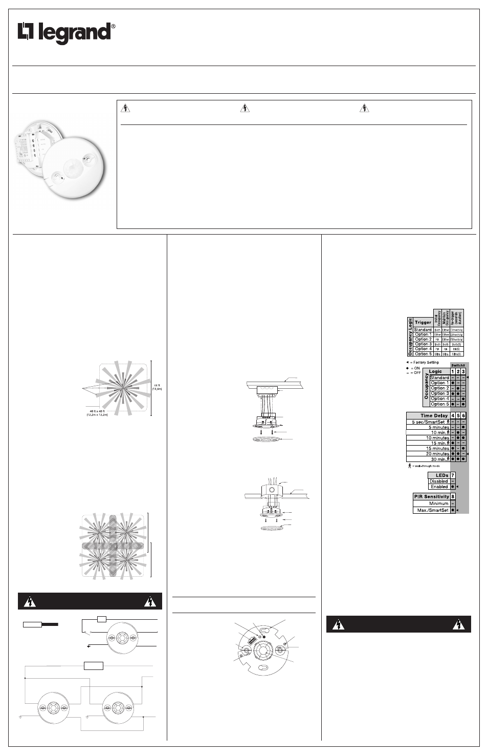
OCCUPANCy lOgIC
The CSD1000LV has 6 logic
configurations for occupancy triggers,
set with DIP switches 1, 2 & 3.
Determine the appropriate Occupancy
Logic Option using the Trigger matrix,
then set the DIP switches accordingly.
Initial Occupancy: The method that
activates a change from “Standby”
(area unoccupied and loads are off) to
“Occupied” (area occupied and loads
are on).
•
Both requires motion detection
by the PIR and the Ultrasonic.
•
Either requires motion detection
by only one technology.
•
PIR requires motion detection by
the PIR.
•
Ultra requires motion detection
by the Ultrasonic.
Maintain Occupancy: The method
indicating that the area is still occupied
and the lights should remain on.
Re-trigger: After the time delay
elapses and the lights turn off,
detection by the selected technology
within the number of seconds
indicated turns the lights back on.
Time Delay: Switches 4, 5, 6
The sensor will hold the lights on as
long as occupancy is detected. The
time delay countdown starts when
no motion is detected. After no motion
is detected for the length of the time
delay, the sensor will turn the lights off.
The sensor can select the time delay
using SmartSet, or you can select a
fixed time delay.
• SmartSet records occupancy
patterns and uses this history to
choose an optimal time delay from 5 to 30 minutes. SmartSet behavior
starts immediately and is refined continually as history is collected.
Walk-through mode turns the lights off three minutes after the area is
initially occupied, if no motion is detected after the first 30 seconds. If
motion continues beyond the first 30 seconds, the selected time delay
applies.
lEds
When enabled, the red PIR and green Ultrasonic Activity LEDs on the
sensor will light when the associated sensor detects motion.
PIR Sensitivity
• Minimum forces a reduced detection range for the PIR.
• Max./SmartSet causes the CSD1000LV to monitor the controlled
environ ment and automatically select the maximum sensitivity that
will provide reliable operation without false detection. This setting is
constantly updated.
TROUBLESHOOTING
CAUTION
Turn power off at the circuit breaker before
working with or near high voltage.
For any unexpected operation
1. Check DIP switch settings.
2. Make sure the switches are set according to the defined settings in the
Logic Configuration Chart.
Lights do not turn on with occupancy, and the following condition
exists:
• Both LEDs do not flash: (DIP switch #7 must be ON to enable the
lEds)
1. Check that the circuit breaker has been turned back on.
2. Check all sensor wire connections.
3. Check for line voltage input to the sensor.
-
If line voltage is present, replace the sensor.
-
If line voltage is not present, check line wiring.
• Red LED does not flash:
When power is initially applied to the sensor, there is a warm-up period
of 30 seconds before the red LED is active.
1. Make sure that PIR Sensitivity is set to 100% (DIP switch #8 set to on).
2. If it still does not flash, call 800.223.4185 for Technical Support.
Hot
Neutral
Neutral
Load
Load
Load
Line
Neutral
Line
Ground
(Optional)
Ground
(Optional)
Three-way wiring
Load
Load
Hot
Neutral
Neutral
Ground
(Optional)
Single sensor, single load
Strip Gauge
#12 to #16 AWG
Cu Wire Only
Drawings not to scale.
Ultrasonic Coverage
PIR Coverage
4" Octagonal,
2.25" Deep*
Junction Box
Ceiling
Sensor
Screws
Front Cover
Mounting to an Octagonal Junction Box
Rear Housing
4" Square
Wiremold #V5752 box
Front Cover
Ceiling
Screws
Sensor Flange
Mounting to a 4" Square box or
4" Square Junction Box with
Double-Gang Mudring
The Junction Box must be at
least 2.25" deep. If it is not, an
extension ring is required.
Keyhole slots
(for mounting to
4" octagonal box)
Double gang
mudring
mounting holes
Light level pushbutton
DIP switches
PIR lens
Ultrasonic
sensitivity
trimpot
ON
1
2
3
4
5
6
7
8
ECE
Ultrasonic
transducer
cones
Ultrasonic
activity
LED (Green)
PIR Activity
LED (Red)
Logic Configuration Chart