Legrand WSP101 User Manual
Pass & seymour
No: 341009 – 8/12 Rev. B
U.S. Patents: 5640113, 6617560
Pass & Seymour
®
Passive Infrared Wall Switch Occupancy Sensor
Détecteur de présence à infrarouges passif avec interrupteur mural
Sensor de ocupación con interruptor a la pared infrarrojo pasivo
Installation Instructions • Instrucciones de Instalación • Notice d’Installation
Catalog Number • Numéro de Catalogue • Le Numéro de Catalogue: WSP101, WSP201
Country of Origin: Made in China • Pays d’origine: Fabriqué en Chine • País de origen: Hecho en China
CAUTION
Turn power off at the circuit breaker before installing
sensor or working on the load.
AVERTISSEMENT
Coupez l’alimentation du disjoncteur avant d’installer
le détecteur ou de travailler sur la charge.
PRECAUCIÓN
Desconecte la alimentación del freno de circuito
antes de instalar el sensor o de trabajar en la carga.
SPECIfICATIONS
Voltages:
WSP101 & WSP201 ......................... 120/277VAC, 50/60Hz
Load Limits for each relay:
@120VAC .....................0-800W tungsten or ballast, 1/6 HP
@277VAC ...................................................0-1200W ballast
Load Type Compatibility:
Incandescent, fluorescent, magnetic or electronic ballast
Horsepower Rating (each relay) .............. 1/6 HP @120VAC
Time Delay Adjustment .................................... 5 to 30 minutes
Walk-Through Mode .....3 minutes if no activity after 30 sec.
Test Mode ........... 5 sec. for 10 min. with DIP switch setting
PIR Adjustment ................................. High or Low (DIP switch)
Light Level Adjustment ........................................ 8fc to 180+fc
Alerts ............................................ Selectable Audible & Visual
SPÉCIfICATIONS
Tensions :
WSP101 & WSP201 ......................... 120/277 V c.a., 50/60 Hz
Limites de charge pour chaque relais :
@120 V c.a. .............. 0-800 W tungstène ou ballast, 1/6 HP
@277 V c.a. ...............................................0-1200 W Ballast
Compatibilité du type de charge :
ballast incandescent, fluorescent, magnétique ou
électronique
Puissance nominale
(pour chaque relais) .............................. 1/6 HP @120 V c.a.
Réglage de la temporisation ............................. 5 à 30 minutes
Mode Passage ............................3 minutes s’il n’y a aucune
activité après 30 secondes
Mode Test ..................................... 5 sec. pour 10 min. avec
réglage d’interrupteur DIP
Réglage PIR .........................Élevé ou faible (interrupteur DIP)
Réglage du niveau de luminosité ..................De 8 fc à 180 +fc
Alarmes ...................................Sonore et/ou visuelle, au choix
ESPECIfICACIONES
Voltajes:
WSP101 y WSP201 ........................ 120/277 VAC, 50/60 Hz
Límites de carga para cada relé:
a 120 VAC ............ Tungsteno o balasto de 0-800 W, 1/6 HP
a 277 VAC ........................................... Balasto de 0-1200 W
Compatibilidad de tipo de carga:
Balasto incandescente, fluorescente, magnético o electrónico
Especificaciones de caballo
de fuerza (cada relé) ................................1/6 HP a 120 VAC
Ajuste del tiempo de retardo........................De 5 a 30 minutos
Modo de Recorrido ................................3 minutos si no hay
actividad después de 30 segundos
Modo de Prueba ........ 5 seg. por 10 min. con configuración
del conmutador selector para bascular
Ajuste PIR........................................Alto o bajo (interruptor del
conmutador selector para bascular)
Ajuste de nivel de luz............................................ 8fc a 180+fc
Alertas ......................................Seleccionable audible y visual
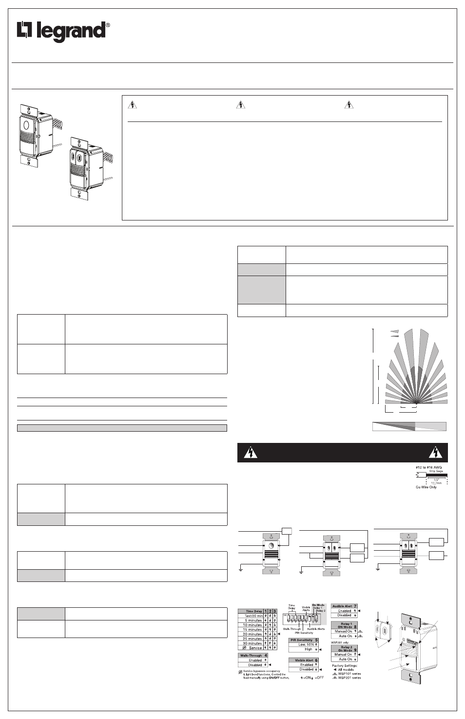
4’
(1.2m)
20’
(6.1m)
35’
(10.6m)
0
Side View
UNIT DESCRIPTION AND OPERATION
The WSP Passive Infrared Wall Switch sensors use advanced passive infrared (PIR) technology.
The WSP sensor can turn a load on, and hold it on as long as the sensor detects occupancy. After no movement
is detected for the selected time delay, the lights switch off. A “walk-through” mode can turn lights off after only 3
minutes, if no activity is detected after 30 seconds following an occupancy detection.
The WSP101 has one relay and one
ON/Off button. The WSP201 contains two relays and two ON/Off buttons to
allow control of one or two loads independently. Pressing a button toggles the state of the corresponding relay.
WSP sensors contain a light level sensor. If adequate daylight is present, the sensor holds the load
Off until light
levels drop, even if the area is occupied. In the WSP201, light level only affects the load on Relay 2. Users can
overrule the hold
Off function by pressing the ON/Off button. See Light Level Adjustment.
Turning Load(s) ON (ON Mode)
The relays are programmed independently for either Auto
ON or Manual ON. In either mode, the load can be turned
ON or Off using the ON/Off button.
Manual ON
DIP 8 ON for Relay 1
DIP 9** ON for Relay 2
With an
ON Mode DIP switch in the ON position, the occupant must press the ON/Off
button to turn
ON the load. The sensor keeps the load ON until no motion is detected for
the selected time delay. There is a 30 second re-retrigger delay. If occupancy is detected
during the delay, the sensor turns the load back
ON. After the re-trigger delay elapses the
ON/Off button must be pressed to turn ON the load.
Auto ON
DIP 8 OFF for Relay 1
DIP 9** OFF for Relay 2
With an
ON Mode DIP switch in the Off position, the load turns ON and Off
automatically based on occupancy. If the load is turned
Off manually, Presentation
Mode operation applies. This prevents the load from turning
ON automatically after it was
deliberately turned
Off. Pressing the button to turn lights ON returns the sensor to Auto
ON mode.
** WSP101: Switch 9 is not used. WSP201: Switch 9 default is
ON to comply with CA Energy Commission Title 24 bi-level switching
requirements.
Model #
Relay
Default ON Mode
DIP switch #
Setting
WSP101
1
Manual ON
8
ON
WSP201
1
2
Auto ON
Manual ON
8
9
OFF
ON
Shading indicates default operation and switch setting.
Presentation Mode is a feature of the Auto ON mode. When both relays are manually turned Off the WSP holds
the lights
Off until no motion has been detected for the duration of the Time Delay. With subsequent occupancy,
the WSP turns the load
ON. If both relays are ON and one relay is manually turned Off this relay remains Off
until both the Time Delay and retrigger delay expires for the relay that is
ON, after that time the ON Mode control
settings again apply.
Time Delays
The WSP sensor holds the load
ON until no motion is detected for the selected time delay. Select the time delay
using DIP switch settings. In the WSP201, both relays use the same delay.
Test/20 min
(DIP 1, 2, 3,
Off)
A Test Mode with a short time delay of 5 seconds is set when DIP switches 1, 2, & 3
are
Off. It cancels automatically after ten minutes, or when you set a fixed time delay.
When the Test Mode times out, the sensor assumes a 20 minute time delay. To restart
Test Mode, change the time delay setting to any fixed amount and then return it to the
Test setting.
fixed Time Delay
(DIP 1 ON, 2 & 3 OFF)
Time delays are 5, 10, 15,
20 (default), 25, or 30 minutes.
Walk-Through
The Walk-Through mode shortens the time delay to reduce the amount of time the load is
ON after a brief moment
of occupancy, such as returning to an office to pick up a forgotten item then immediately exiting.
Walk-Through Mode
(DIP #4 ON)
The WSP sensor turns the load
Off three minutes after the area is initially occupied, if
no motion is detected after the first 30 seconds. If motion continues beyond the first 30
seconds, the set time delay applies.
No Walk-Through
DIP #4 OFF)
Walk-Through mode disabled.
PIR Sensitivity Adjustment
The WSP sensor constantly monitors the controlled environment and automatically adjusts the PIR to avoid
common ambient conditions that can cause false detections, while providing maximum coverage.
Walk-Through Mode
(DIP #4 ON)
Default setting. Suitable for most applications.
Low, 50%
(DIP #5
ON)
Reduces sensitivity by approximately 50%. Useful in cases where the PIR is detecting
movement outside of the desired area (also consider masking the lens) and where heat
sources cause unnecessary activation.
Alerts
The WSP can provide audible and/or visible alerts as a warning before the load turns OFF.
Visible Alert
(DIP #6
ON)
When only one minute is left in the time delay, the load connected to the relay turns
Off for one second. This provides a one minute warning before the load(s) are turned
Off by the sensor.
No Visible Alerts
(DIP #6
Off)
No visible warnings provided.
Audible Alerts
(DIP #7
ON)
Unit will beep at one minute*, at 30 seconds and at 10 seconds before turning
Off
load. When Walk-Through is active, the unit beeps three times at 10 seconds before the
load goes
Off.
* If Visible Alert is also
ON, the one-minute time-out warning beep is replaced by the
visible alert.
No Audible Alerts
(DIP #7
Off)
No audible warnings provided.
COVERAgE PATTERNS
Coverage testing has been performed according to the NEMA
WD 7 guideline. For best performance, use in spaces not larger
than 15' x 12'.
PIR Sensor
The sensor has a two-tiered, multi-cell viewing Fresnel lens with
180 degree field of view. The red LED on the sensor flashes when
the PIR detects motion.
Masking the lens
Opaque adhesive tape is supplied so that sections of the PIR
sensor’s view can be masked. This allows you to eliminate
coverage in unwanted areas. Since masking removes bands of
coverage, remember to take this into account when troubleshooting
coverage problems.
INSTALLATION
WARNINg
Turn the power off at the circuit breaker before installing the sensor
or working on the load.
1. Make sure that the power has been turned
Off at the circuit breaker.
2. Connect wires to the WSP flying leads as shown in the wiring diagram that is
appropriate to the WSP model and electrical supply.
The 2 ground wires (green
and green/yellow) must be fastened to ground for the sensor to work properly.
3. Attach the sensor to the wall box by inserting screws into the two wide holes on the
top and bottom of the attached metal bracket. Match them up with the holes in the wall box and tighten.
4. Turn the circuit breaker
ON. Wait one minute, then push the Auto ON/Off switch for each load and the lights will
turn
ON. There is a delay due to initial power-up of the sensor that only occurs during installation.
5. Test and adjust the sensor if necessary.
6. Install industry standard decorator wall switch cover plate (not included).
WSP201 Bi-Level Wiring
Neutral
Blue
Line
Black
Secondary
Load
Brown
Primary
Load
Red
Ground
Green
Neutral White
Azul
Carga
principal
Carga
secundaria
Neutro
Rojo
Marrón
Línea 2
Línea 1
Neutro
Tierra
Verde
Negro
Neutro
Blanco
WSP201 Dual Circuit Wiring
Load
Red
Neutral White
Neutral
Ground
Green
Line Black
WSP101 Wiring
DIP SWITCh SETTINgS
DELA
Y
PIR 50%
WA
LK
AUD. ALERT
RL
Y 1 MAN
RL
Y 2 MAN
VIS. ALERT
DIP Switches
ON/Off Buttons
Relay 1
Relay 2
PIR Lens
Detection
LED
Button
hinges
Tabs
WSP201 shown.
WSP101 has a single button.
WSP101
WSP201
PIR
Coverage
7.5’
(2.2m)
15’
(4.5m)
20’
(6.1m)
35’
(10.6m)
Major motion
Minor motion
Top View