Legrand PW1012 User Manual
Is-0551 rev. b
INSTRUCTION / INSTALLATION SHEET
Universal Power Distribution Module
(P/N PW1012)
IS-0551 Rev. B
301Fulling Mill Road, Suite G
Middletown, PA 17057
Phone (800) 321-2343 / Fax (717) 702-2546
www.legrand.us
©Copyright 2012 by Legrand All Rights Reserved.
Page 1 of 1
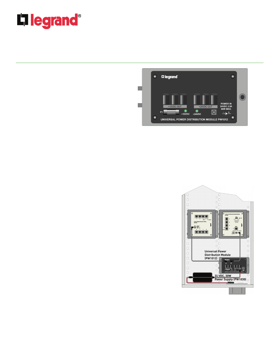
Figure 1
1.
INTRODUCTION
The Legrand Universal Power Distribution Module, P/N
PW1012, (see Figure 1) allows you to power a wide variety
of modules and devices and is a low cost alternative to the
PW1010.
2.
FEATURES
• The Universal Power Distribution Module supplies:
– Three 12VDC output connections at 2A max
– Three 24VDC output connections at 2.5A max
• Includes one P/N PW1030 24VDC, 30W power supply
NOTE: May also be used with P/N PW1060 24VDC, 60 W
power supply (available separately)
• Includes three 24" 2.5mm low voltage power cord jumpers
NOTE: Additional DC power cord jumpers (P/N F7716) available separately
• Includes single bay bracket (P/N 364890-01) for mounting in On-Q style enclosure
• Includes one spare 24VDC power over-current protection 3A rated fuse
• Output 12VDC power monitoring via sense circuits which control an enable line to the DC-DC convertor chip
• Green “+24VDC” LED to indicate operation of the input power supply and UPDM
• Green “+12VDC” LED to indicate status of the +12V output
3.
POWER REQUIREMENTS / INDICATIONS
When +24VDC power is present from the included PW1030, the green “+24VDC” led will
be on to indicate total output loading is within the 3A fuse’s rating.
When any +12VDC output channel exceeds its 2.0A limit, the output will shut down and
the “+12VDC” led will blink dimly. If a +12VDC output is shorted, the “+12VDC” led will
appear to be turned off.
NOTE: The PW1012 Universal Power Distribution Module is intended for indoor
use only.
NOTE: When total module current exceeds 3A, the fuse will open and need to be
replaced with the included spare fuse, however, before replacing the fuse, remove
all DC power cables, and re-install them one-by-one after determining that the total
sum of DC output draw is less than 3A for all output loads combined.
4.
INSTALLATION
Refer to the example shown in Figure 2 during installation.
A. Snap the PW1012 Universal Power Distribution Module onto the included
bracket using the push-pins at each corner.
B. Without mounting the module, find the appropriate spot in the enclosure where
all the power cord jumpers reach the modules to be powered.
C. Mount the module/bracket into the enclosure, insert the tabs on the left side of
the bracket into the slots in the enclosure and push the bracket pushpin into an
appropriate hole in the enclosure to secure the module/bracket to the
enclosure.
D. Make the appropriate connections with the power cord jumpers.
E.
Connect the input power cable to the module and plug the power supply into
the AC input receptacle.
Figure 2