Legrand LSCL450 User Manual
Pass & seymour, Instructions en français
No: 341089 – 8/14
Pass & Seymour
®
TradeMaster
®
Dimmers: CFL/LED 450W, 120VAC, 60 Hz; Incandescent 700W,
120VAC, 60 Hz
TradeMaster
®
Variateurs : CFL/LED 450 W, 120 VCA, 60 Hz; Incandescents
700 W, 120 VCA, 60 Hz
TradeMaster
®
Reductores: CFL/LED 450 W, 120 VCA, 60 Hz; Incandescente
700 W, 120 VCA, 60 Hz
Installation Instructions • Instrucciones de Instalación • Notice d’Installation
Catalog Number(s) • Numéro(s) de Catalogue • Les Numéros de Catalogue: LSCL450, LSCL453P
Country of Origin: Made in China • Pays d’origine: Fabriqué en Chine • País de origen: Hecho en China
5. Install dimmer in wall box, with word ‘TOP’ on the strap right side up, using
mounting screws provided.
6. Attach wall plate, then restore power to circuit.
7. Dimmer may require adjustment to the low end setting to reliably start and/or
remove flickering in bulbs. To adjust, DISCONNECT POWER FROM CIRCUIT, and
remove the Wallplate. Use a small insulated, flat tipped screwdriver to adjust the
trim pot wheel, which is accessible via the slot (marked “CALIBRATION”) provided
on the strap (Figure 1). Turn the wheel
downwards to increase the minimum light
intensity setting and turn the wheel
upwards to decrease light intensity. Next,
install the Wallplate, restore the power and test. Repeat above as necessary.
Note: Never adjust trim pot when circuit is live. To
re-calibrate settings turn the trim pot wheel all the way up
towards the “-” sign and incrementally progress to “+” sign
until flickering is removed (refer to Step 7 above).
Note: It is normal for the dimmer to feel warm during operation.
Use a separate neutral wire for each phase of a multiphase
system containing a dimmer, and for high power single phase
applications where flickering is present.
Any combination of dimmers and other devices may be ganged
together.
ADDING A LIGHT MODULE (sold separately, Catalog #TM8LMCC)
Transform in minutes a standard dimmer into an illuminated dimmer
(ON when light is OFF) – allows the dimmer to be found in the dark.
Average 20-year life expectancy.
No wiring – quick snap-in installation.
Figure 1
IMPORTANT NOTES:
1. All dimmers can be damaged by improper wiring. Check for short circuits prior to
installing the dimmer.
Procedure for short circuit check:
a. Disconnect power to circuit by removing fuse or turn circuit breakers OFF.
b. Install a switch instead of the dimmer. Turn the switch to the “ON” position.
c. Turn power ON. If the circuit breaker trips, a short is present. If the light fails to
turn ON and OFF with the switch, the wiring may be incorrect.
d. Correct wiring, if necessary and retest.
e. Install the dimmer only after the light operates properly with the switch.
2. Protect from dirt and dust. The dimmer can be damaged from contaminates
encountered during the construction process. If lighting is required prior to the
construction process completion, then a switch should be temporarily installed
in place of the dimmer. The dimmer should not be installed until the construction
process is complete.
Any dimmer damage due to improper installation is not covered under warranty.
Directions
1. Disconnect power to circuit by removing fuse or turn circuit breakers OFF before
installing.
2. Remove wall plate and switch mounting screws, pull existing switch from wall box.
3. Disconnect existing switch from circuit. 3-way installation: Identify the “Common”
wire (wire connected to the terminal marked common or odd colored terminal).
For “new” installation identify wire connected to power source or to the load.
4. Connect dimmer as shown in the installation diagram using #12 or #14 AWG
stranded or solid copper conductors. Strip wire using gauge on back of device.
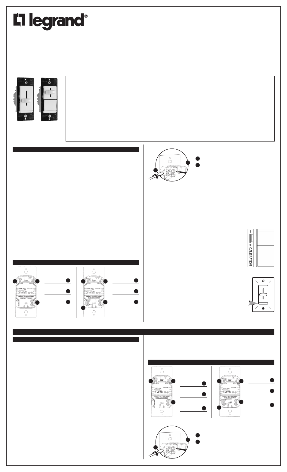
INSTALLATION DIAGRAM FOR DIMMERS
Single Pole
3-Way
2
3
1
Wire to Source
120VAC 60Hz
1
Ground Wire
(Green or Bare)
2
Wire to Light
120VAC 60Hz
3
Common Wire
(Black)
1
Ground Wire
(Green or Bare)
2
Traveler Wire to
3-Way Switch
3
1
3
2
3
LSCL450 LSCL453P
INSTRUCTIONS EN FRANÇAIS
REMARQUES IMPORTANTES :
1. Tous les gradateurs peuvent être endommagés par un câblage incorrect. Vérifier
qu’il n’y a pas de court-circuit avant d’installer le régulateur.
Comment vérifier l’absence de court-circuit :
a. Couper l’alimentation du circuit en retirant le fusible ou en ouvrant les
disjoncteurs (ARRÊT / OFF).
b. Installer un interrupteur à la place du gradateur. Mettre l’interrupteur en position
fermée (MARCHE / ON).
c. Rétablir l’alimentation électrique. Si le disjoncteur saute, c’est qu’il existe un
court-circuit. Si la lumière ne s’allume ou ne s’éteint pas correctement, le câblage
peut être incorrect.
d. Rectifier le câblage si besoin est, et retester le circuit.
e. Installer le gradateur uniquement si la lumière fonctionne correctement avec
l’interrupteur.
2. Protéger le dispositif de la saleté et de la poussière. Le gradateur peut être
endommagé par des débris laissés au cours de la construction. S’il est
nécessaire d’avoir une source d’éclairage avant la fin de la construction, installer
provisoirement un interrupteur à la place du gradateur. Le gradateur ne doit pas être
installé avant la fin de la construction.
Aucun gradateur endommagé par une installation incorrecte n’est couvert par
la garantie.
INSTRUCTIONS :
1. Couper l’alimentation du circuit au tableau en enlevant le fusible ou en mettant
l’interrupteur en position ARRET avant installation.
2. Enlever la plaque murale et les vis de montage de l’interrupteur, retirer l’interrupteur
existant du coffret mural.
3. Déconnecter l’interrupteur existant du circuit. Installation à trois niveaux: Identifier
le fil “COMMUN” (fil connecté à la borne marquée “commun” ou borne de couleur
différente des autres). Pour une installation “nouvelle”, identifier le fil connecté à la
source d’alimentation ou à la charge.
4. Raccorder l’atténuateur comme indiqué sur le diagramme d’installation, en utilisant
du fil ou du cable électrique en cuivre #12 ou 14 AWG. Dénuder les fils selon
l’indicateur sur l’arrière de l’appareil.
DIAGRAMME D’INSTALLATION POUR GRADATEURS
Unipolaire
3 voies
2
3
1
Raccorder
à la source
120 VCA 60 Hz
1
Fil de Terre
(vert ou nu)
2
Raccorder
à la lampe
120 VCA 60 Hz
3
Fill commun
(noir)
1
Fil de Terre
(vert ou nu)
2
Commun vers
l’interrupteur
3 voies
3
1
3
2
3
Fil arrière avec vis et plaque de pression
1
Insèrer le fil jusqu’au fond du trou.
2
Serrer la vis fermement sous le trou du fil pour
retenir le fil insère.
Les terminaux acceptent des conducteurs fil ou cable
en cuivre #12 ou #14 AWG.
2
1
Screw Pressure Plate Back Wire
1
Insert wire to bottom of hole.
2
Securely tighten screw beneath wire hole to retain
inserted wire.
Termination takes #12 or #14 AWG stranded or solid,
copper conductors.
2
1
LIRE ET CONSERVER CES INSTRUCTIONS
Doit être installé par un électricien certifié ou une autre personne
qualifiée.
AVERTISSEMENT – Pour éviter tout choc électrique ou une
électrocution, toujours couper l’électricité au niveau du panneau
d’alimentation avant d’installer cette unité, de travailler sur le
circuit électrique ou de changer une lampe.
ATTENTION : Pour réduire le risque de surchauffe ou
d’endommagement d’autres pièces d’équipement :
• Ne pas installer un gradateur pour contrôler une prise
électrique, ou un appareil ménager équipé d’un moteur ou
alimenté par un transformateur.
• À n’utiliser qu’avec des ampoules à incandescence ou variable
à luminosité CFL_LED ampoules compatibles qui se vissent
dans des douilles d’ampoules à incandescence traditionnelles
(ampoules compatibles énumérés à www.legrand.us).
Connecter à une source de 120 VCA, 60 Hz uniquement.
Une charge minimale de 10W est recommandée pour un
fonctionnement optimal du gradateur.
N’utiliser que des fils en cuivre.
LEA Y CONSERVE ESTAS INSTRUCCIONES
Para ser instalado por un electricista certificado o persona
competente.
ADVERTENCIA – Para evitar descargas eléctricas serias o
electrocución, antes de instalar, trabajar en el circuito o cambiar
una lámpara de este atenuador apague siempre el suministro
eléctrico en el panel de servicio.
PRECAUCIÓN: Para reducir el riesgo de sobrecalentamiento
y posibles daños a otros equipos:
• No instale un atenuador para controlar un tomacorriente,
un electrodoméstico que funciona con motor o un
electrodoméstico con transformador.
• Utilícese solamente con bombillas incandescentes CFL o LED
atenuables que se atornillan en portalámparas incandescentes
convencionales (bombillas compatibles enumerados en www.
legrand.us).
Conecte solamente a un suministro eléctrico de 120 VAC, 60 Hz.
Una carga minima de 10W se recomienda para un
funcionamiento óptimo del atenuador.
Utilice únicamente alambres de cobre.
READ AND SAVE THESE INSTRUCTIONS
To be installed by a certified electrician or other
qualified person.
WARNING – To prevent severe shock or electrocution,
always turn power off at the service panel before
installing this unit, working on the circuit, or changing
a lamp.
CAUTION: To reduce the risk of overheating and
possible damage to other equipment:
• Do not install dimmer to control a receptacle, a
motor-operated appliance or a transformer-supplied
appliance.
• Use only with incandescent or compatible dimmable
CFL/LED bulbs which screw into conventional
incandescent lamp sockets (compatible bulbs listed
at www.legrand.us).
Connect to 120VAC, 60 Hz power source only.
A minimum load of 10W is recommended for optimal
operation of the dimmer.
Use copper wire only.