Legrand HCL453PTC User Manual
Harmony, Cfl/led dimmers, Installation instructions
READ AND SAVE THESE INSTRUCTIONS
To be installed by a certified electrician or other qualified person.
WARNING – To prevent severe shock or electrocution, always turn power off at the service panel
before installing this unit, working on the circuit, or changing a lamp.
CAUTION
To reduce the risk of overheating and possible damage to other equipment:
• Do not install dimmer to control a receptacle, a motor-operated appliance, or a transformer-
supplied appliance.
• Use only with compatible dimmable CFL or LED bulbs (compatible bulbs listed in table below).
The dimmer is to be used with dimmable CFL and dimmable LED bulbs which screw into conventional
incandescent lamp sockets. Connect to 120VAC, 60 Hz power source only.
A 10W minimum load is required.
Use copper wire only.
Dimmer is compatible with the following bulbs: / El atenuador es compatible con las siguientes
bombillas:
/ Le gradateur est compatible avec les ampoules suivantes :
CFL
Brand
Model
Bulb Description
Ecosmart
ES5CCDF052 (8TC05)
5W Candle
ES5M814DIM2 (40114 )
14W Spiral
ES5M10123 (10123)
23W Spiral
BPESL11R20/DIM/ESM (2R2014DIM)
11W R20 Flood
ES5R315DIM50K (2R3015DIM)
15W R30 Flood
ES5R315DIM35K (2R3015DIM)
15W R30 Flood
ES5R214DIM50K (2R2014DIM)
14W R20 Flood
Feit
BPESL15T/DM
15W Spiral
BPESL23T/DM
23W Spiral
Bright Effects
LBP13TC/DM
13W Spiral
GE
FLE15HT3/2/DV/SW
15W Spiral
FLE26HT3/2/DV/SW
26W Spiral
FLE26/2/DV/R40
26W R40 Flood
Philips
EL/A PAR38 DIM 20W
20W PAR38 Flood
EL/A R30 DIM 16W
16W R30 Flood
EL/A R40 DIM 20W
20W R40 Flood
EL/mdT DIM 15W
15W Spiral
EL/mdT DIM 20W
20W Spiral
TCP
2R2014DIM
14W Spiral R20
2R3016DIM
16W Spiral R30
2R4019DIM
19W Spiral R30
8A08WH
8W A19
8TC05F
5W Candle
8T03CL
3W Candle
40114
14W Spiral
40123
23W Spiral
Sylvania
CF5EL/DECO/DIM
5W Candle
CF14EL/TWIST/827/DIM
14W Spiral
CF14EL/R20/DIM
14W R20
CF15EL/BR30/DIM
15W R30 Flood
CF19EL/BR40/DIM
19W R40 Flood
CF24EL/TWIST/DIM
24W Spiral
Halco
CFL15/27/DIM
15W T4 Mini-Spiral
CFL15/27/R30/DIM
15W R30 Flood
CFL23/27/DIM
23W T3 Mini-Spiral
CFL23/27/R40/DIM
23W R40 Flood
LED
Brand
Model
Bulb Description
Ecosmart
ECS 19 WW 120
8.6W A19
ECS 25 WW 120
8W G25
ECS 20 WW FL 120
8W PAR20
ECS 30 WW FL 120
15W PAR30
ECS 38 WW FL 120
18W PAR38
(CREE) ECO-575L
10.5W Downlight
Philips
11E26PAR30S-E
3W Candle
12EPAR30S-E1
3W Candle
7E26PAR20-E
6W R20 Flood
3E12B11-E
7W PAR20 Flood
7E26A60
7W A19
6E26R20
8W A19
3E12BA11-E
11W PAR30S Flood
8E26A60
12W PAR30S Flood
17E26PAR38-E1
16W PAR38 Flood
16E26PAR38-E
17W PAR38 Flood
Sylvania
LED8A/DIM/F/830
8W A19
LED8/PAR20/DIM/830/NFL25
8W PAR20
LED8/G25/DIM/F/830
8W G25
LED15/PAR30LN/DIM/830/NFL25
15W PAR30
LED18/PAR38/DIM/830/NFL25
18W PAR38
Halco
PAR16/6NW/FL/LED2
6W PAR16
PAR20/8NW/NFL/LED2
8W PAR20
PAR30/14WW/SP/LED2
14W PAR30
PAR38/18WW/FL/LED
18W PAR38
Color Change Procedure / Procedimiento de Cambio de Color /
Procédure de Changement de Couleur
Directions
1. If a color change kit was provided, and a different color is desired, see the Color Change Procedure,
if not proceed to step #2.
2. Disconnect power to circuit by removing fuse or turn circuit breakers OFF before installing.
3. Remove wall plate and switch mounting screws, pull existing switch from wall box.
4. Disconnect existing switch from circuit. For 3-way installations: Identify the “Common” wire (wire
connected to the terminal marked common or odd colored terminal). For new installation identify
wire connected to power source or to the load.
5. Connect dimmer as shown in the installation diagram using #12 or #14 AWG stranded or solid
copper conductors. Strip wire using gauge on back of device.
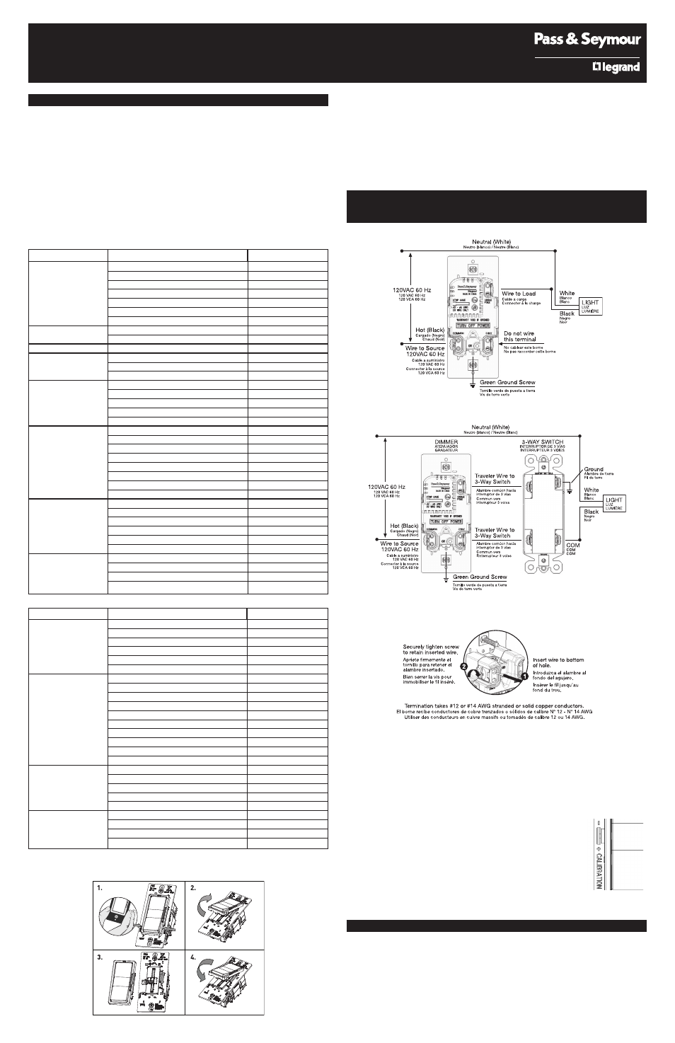
INSTALLATION DIAGRAM FOR DIMMERS
DIAGRAMA DE INSTALACIÓN PARA ATENUADORES
SCHÉMA D’INSTALLATION DES GRADATEURS
Single Pole Installation / Instalación unipolar / Installation unipolaire
3-Way Installation / Instalación de 3 vías / Installation 3 voies
Screw Pressure Plate Back Wire / Cable trasero con tornillo y placa de presión /
Fil arrière avec vis et plaque de pression
6. Install dimmer in wall box, with word “TOP” on the strap right side up, using mounting screws
provided.
7. Attach wall plate and then restore power to circuit.
8. Dimmer may require adjustment to the low end setting to reliably start and/or remove flickering
in bulbs. To adjust, DISCONNECT POWER FROM CIRCUIT, and remove the Wallplate. Use a small
insulated, flat tipped screwdriver to adjust the trim pot wheel, which is accessible via the slot
(marked “CALIBRATION”) provided on the strap. Turn the wheel downwards to increase the
minimum light intensity setting and turn the wheel upwards to decrease light intensity. Next,
install the Wallplate, restore the power and test. Repeat above as necessary.
Note: Never adjust trim pot when circuit is live. To re-calibrate
settings turn the trim pot wheel all the way up towards the “-” sign and
incrementally progress to “+” sign until flickering is removed (refer to
Step 8 above).
Note: This device should be installed after sheet rocking and painting
are completed.
Note: It is normal for the dimmer to feel warm during operation. Use a
separate neutral wire for each phase of a multiphase system containing
a dimmer, and for high power single phase applications where flickering
is present.
Any combination of dimmers and other devices may be ganged together.
IMPORTANT NOTES:
1. All dimmers can be damaged by improper wiring. Check for short circuits prior to installing the
dimmer.
Procedure for short circuit check:
a. Disconnect power to circuit by removing fuse or turn circuit breakers OFF.
b. Install a switch instead of the dimmer. Turn the switch to the “ON” position.
c. Turn power ON. If the circuit breaker trips, a short is present. If the light fails to turn ON and
OFF with the switch, the wiring may be incorrect.
d. Correct wiring, if necessary and retest.
e. Install the dimmer only after the light operates properly with the switch.
HARMONY
™
CFL/LED DIMMERS
INSTALLATION INSTRUCTIONS
P/N 340930
Figure 1 / Figura 1 / Figure 1
Figure 2 / Figura 2 / Figure 2
Figure 3 / Figura 3 / Figure 3
Figure 4 / Figura 4 /
Figure 4