Legrand WS4FBL3P User Manual
Pass & seymour, Instructions en français, Fluorescent or led slide dimmer
No: 341117 – 03/15
Pass & Seymour
®
Wide Slide Fluorescent/LED Dimmers: 10A, 120VAC, 60Hz or 5A, 277VAC, 60Hz
Grands gradateurs à glissière pour fluorescent/DEL : 10 A, 120 V c.a., 60 Hz ou 5 A, 277 V c.a., 60 Hz
Grandes atenuadores deslizantes para fluorescente/LED: 10A, 120VAC, 60Hz o 5A, 277VAC, 60Hz
Installation Instructions • Notice d’Installation • Instrucciones de Instalación
Catalog Number • Numéro de Catalogue • Número de Catálogo: WS4FBL3P
Country of Origin: Made in China • Pays d’origine: Fabriqué en Chine • País de origen: Hecho en China
IMPORTANT NOTES:
FLUORESCENT OR LED SLIDE DIMMER
1. All dimmers can be damaged by improper wiring. Check for short circuits prior to installing
the dimmer with a lamp load in the circuit.
Procedure for short circuit check:
a. Disconnect power to circuit by removing fuse or turn circuit breakers OFF.
b. Connect the violet ballast wire direct to the gray ballast wire.
c. Install a switch instead of the dimmer. Turn the switch to the “ON” position.
d. Turn power ON. If the circuit breaker trips, a short is present. If the light fails to turn ON
and OFF with the switch, the wiring may be incorrect.
e. Correct wiring, if necessary and retest.
f. Install the dimmer only after the light operates properly with the switch.
2. Protect from dirt and dust. The dimmer can be damaged from contaminates encountered
during the construction process. If lighting is required prior to the construction process
completion, then a switch should be temporarily installed in place of the dimmer. The
dimmer should not be installed until the construction process is complete.
Any dimmer damage due to improper installation is not covered under warranty.
COLOR CHANGE PROCEDURE/PROCÉDURE DE CHANGEMENT DE
COULEUR/PROCEDIMIENTO DE CAMBIO DE COLOR
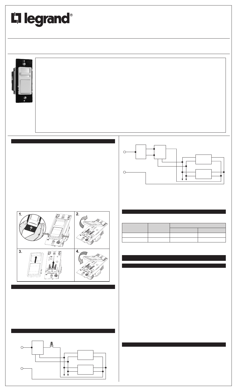
DIRECTIONS:
1. If a color change kit was provided, and a different color is desired, see the Color Change
Procedure, if not proceed to step #2.
2. Disconnect power to circuit at the panel by removing fuse or turn circuit breakers OFF
before installing.
3. Remove wall plate and switch mounting screws, pull existing switch from wall box.
4. Disconnect existing switch from circuit. 3-Way installation: Identify the “COMMON” wire
(wire connected to the terminal marked common or odd colored terminal). For “new”
installation identify wire connected to power source or to the load (Figure 2).
5. Connect dimmer as shown in the wiring diagram using #12 or #14 AWG stranded or solid
copper conductors (Figure 1).
NOTE: Cap off the 3-way wire with a wire nut in a single pole installation.
WIRING DIAGRAMS FOR DIMMERS
6. Install dimmer in wall box, with word ‘TOP’ on the strap right side up, using mounting
screws provided.
7. Attach wall plate and restore power to circuit.
NOTE: It is normal for the dimmer to feel warm during operation. Use a separate neutral wire
for each phase of a multiphase system containing a dimmer, and for high power single phase
applications where flickering is present.
MULTIPLE GANGING OF DIMMERS AND OTHER DEVICES
Any combination of dimmer models and other devices may be ganged together. De-rate the
maximum load according to the following table:
Dimmer Catalog #
Maximum Load
Multi-Gang Derating
2 Gang Installation
3 Gang Installation
WS4FBL3P (120V)
10A
10A
10A
WS4FBL3P (277V)
5A
5A
5A
INSTRUCTIONS EN FRANÇAIS
REMARQUES IMPORTANTES :
GRADATEUR À GLISSIÈRE POUR DEL OU FLUORESCENT
1. Tous les gradateurs peuvent être endommagés par un câblage incorrect. Avant d’installer
le gradateur, vérifier qu’il n’y a pas de court-circuit en utilisant une lampe.
Comment vérifier l’absence de court-circuit :
a. Couper l’alimentation du circuit en retirant le fusible ou en ouvrant les disjoncteurs
(ARRÊT/OFF).
b. Raccordez le fil de ballast violet directement au fil de ballast gris.
c. Installer un interrupteur à la place du gradateur. Mettre l’interrupteur en position fermée
(MARCHE/ON).
d. Rétablir l’alimentation électrique. Si le disjoncteur saute, c’est qu’il existe un court-
circuit. Si la lumière ne s’allume ou ne s’éteint pas correctement, le câblage peut
être incorrect.
e. Rectifier le câblage si besoin est, et retester le circuit.
f. Installer le gradateur uniquement si la lumière fonctionne correctement avec
l’interrupteur.
2. Protéger le dispositif de la saleté et de la poussière. Le gradateur peut être endommagé
par des débris laissés au cours de la construction. S’il est nécessaire d’avoir une source
d’éclairage avant la fin de la construction, installer provisoirement un interrupteur à la
place du gradateur. Le gradateur ne doit pas être installé avant la fin de la construction.
Aucun gradateur endommagé par une installation incorrecte n’est couvert par la
garantie.
INSTRUCTIONS :
1. S’il est nécessaire de changer de couleur et qu’un ensemble de changement de couleur
est disponible, se reporter à la Procédure de changement de couleur; sinon, passer à
l’étape n° 2.
2. Couper l’alimentation du circuit en retirant le fusible ou en ouvrant les disjoncteurs
(ARRÊT/OFF) avant de commencer l’installation.
3. Retirer les vis de fixation de la plaque murale et de l’interrupteur, puis retirer l’interrupteur
de la boîte murale.
READ AND SAVE THESE INSTRUCTIONS
To be installed by a certified electrician or other qualified
person.
WARNING – To prevent severe shock or electrocution, always
turn power off at the service panel before installing this unit,
working on the circuit, or changing a lamp.
CAUTION – To reduce the risk of overheating and possible
damage to other equipment, do not install incandescent dimmer
to control a receptacle, a fluorescent light or bulb, a motor-
operated appliance, or a transformer-supplied appliance.
• Do not use dimmer with lamps whose power requirements
exceed maximum power (stated in Amps) of the dimmer.
• Connect dimmer and ballast to power source compatible with
ballast markings.
• Use copper wire only.
• A maximum of 30 ballasts can be connected to a single
dimmer control.
• This dimmer is compatible with UL Listed 120VAC or 277VAC
rated, 0-10V dimmable ballasts. For example, Advance
transformer Mark 7™ or Osram Sylvania Quicktronic Helios.
• Use Class 2 wiring. Do not run Class 2 wires in the same
conduit as line voltage conductors.
LIRE ET CONSERVER CES INSTRUCTIONS
Doit être installé par un électricien certifié ou une autre
personne qualifiée.
AVERTISSEMENT – Pour éviter tout choc électrique ou une
électrocution, toujours couper l’électricité au niveau du panneau
d’alimentation avant d’installer cette unité, de travailler sur le
circuit électrique ou de changer une lampe.
ATTENTION – Pour éviter toute surchauffe et endommagement
éventuel des autres appareils, ne pas utiliser pour contrôler
une prise, une lampe ou un tube fluorescent, ou un appareil
ménager équipé d’un moteur ou alimenté par un transformateur.
• Ne pas utiliser ce gradateur avec des lampes d’une
puissance supérieure à la puissance maximale (exprimée en
amps) de ce gradateur.
• Raccordez le gradateur et le ballast à une source
d’alimentation compatible avec les marquages sur le ballast.
• N’utiliser que des fils en cuivre.
• 30 ballasts au maximum peuvent être raccordés à une seule
commande de gradation.
• Ce gradateur est compatible avec les ballasts à intensité
réglable de 0 à 10 V homologués UL 120 V c.a. ou 277 V
c.a. Par exemple, Advance Mark 7™ ou Osram Sylvania
Quicktronic Helios.
• Utilisez un câblage de classe 2. Ne faites pas passer de fils
de classe 2 dans le même conduit que des conducteurs à la
tension du secteur.
LEA Y CONSERVE ESTAS INSTRUCCIONES
Para ser instalado por un electricista certificado o persona
competente.
ADVERTENCIA – Para evitar descargas eléctricas serias o
electrocución, antes de instalar, trabajar en el circuito o cambiar
una lámpara de este atenuador apague siempre el suministro
eléctrico en el panel de servicio.
PRECAUCIÓN – Para reducir el riesgo de sobre calenta miento
y posibles daños a otros equipos, no instale un atenuador de
lámparas incandescentes para controlar un tomacorriente,
una lámpara o bombilla fluorescente, un electrodoméstico
operado mediante motor o un electrodoméstico equipado con
transformador.
• No utilice atenuadores con lámparas cuyos requerimientos
de suministro eléctrico excedan la potencia máxima (indicada
en A) del atenuador.
• Conecte el regulador y el balasto a una fuente de
alimentación compatible con marcas para balastos.
• Utilice únicamente alambres de cobre.
• Se puede conectar un máximo de 30 balastos a un control
de regulador simple.
• El regulador es compatible con los balastros regulables
calificados por UL como aptos para 120 VAC o de 277 VAC
y de 0 a 10 V. Por ejemplo, transformadores Advance Mark
7™ u Osram Sylvania Quicktronic Helios.
• Utilice cableado Clase 2. No extienda cables Clase 2 en el
mismo conducto que los conductores del voltaje de línea.
Red
Black
DIMMER
DIMMING
BALLAST
DIMMING
BALLAST
Gray
Gray
Neutral
Purple
White
Black
White
Purple
Gray
Purple
Black
Hot
Black
Figure 1 – Single Pole Wiring
Red
Red
Black
DIMMER
DIMMING
BALLAST
3-Way
Switch
DIMMING
BALLAST
Gray
Gray
Neutral
Purple
White
Black
White
Hot
Black
Purple
Gray
Purple
Figure 2 – 3-Way Wiring