Legrand T600EI User Manual
Installation & operating instructions, Instructions dʼinstallation et dʼutilisation
Read and save these instructions
Wiring and Installation Diagrams Below
For Use with Models: T600E, T1000E
CAUTION
To avoid overheating and possible damage to equipment do not install this device to control a
receptacle, a fluorescent lighting fixture, a motor operated appliance, or a transformer-supplied
appliance.
Notice: Use only copper wire with these devices.
This control is intended for installation in a UL-Listed metal or plastic (polymeric) outlet box.
INSTALLATION
1. Disconnect power to circuit by removing fuse or turning circuit breakers to OFF before installing.
2. Remove existing wall plate and switch.
3. Strip wires to 1/2" for size 14 or bigger, 5/8" for 16 or smaller.
4. Install dimmer as shown with wire connectors provided.
5. Replace dimmer in wall box.
6. Replace wall plate.
7. Place toggle in the OFF position before restoring power to circuit.
MAXIMUM LOAD PER DIMMER FOR MULTI-GANG
CAT. NO.
SINGLE
2-GANG
More than 2-GANG
T600E
600W
500W
400W
T1000E
1000W
800W
700W
OPERATION
1. To turn ON:
Single Pole: Flip toggle up.
3-Way: Flip toggle up or down until LED goes OFF and/or light turns ON.
2. Touch upper or lower touch pad to adjust lighting level.
3. To turn OFF:
Single Pole: Flip toggle down.
3-Way: Flip toggle up or down until LED goes ON and/or light turns OFF.
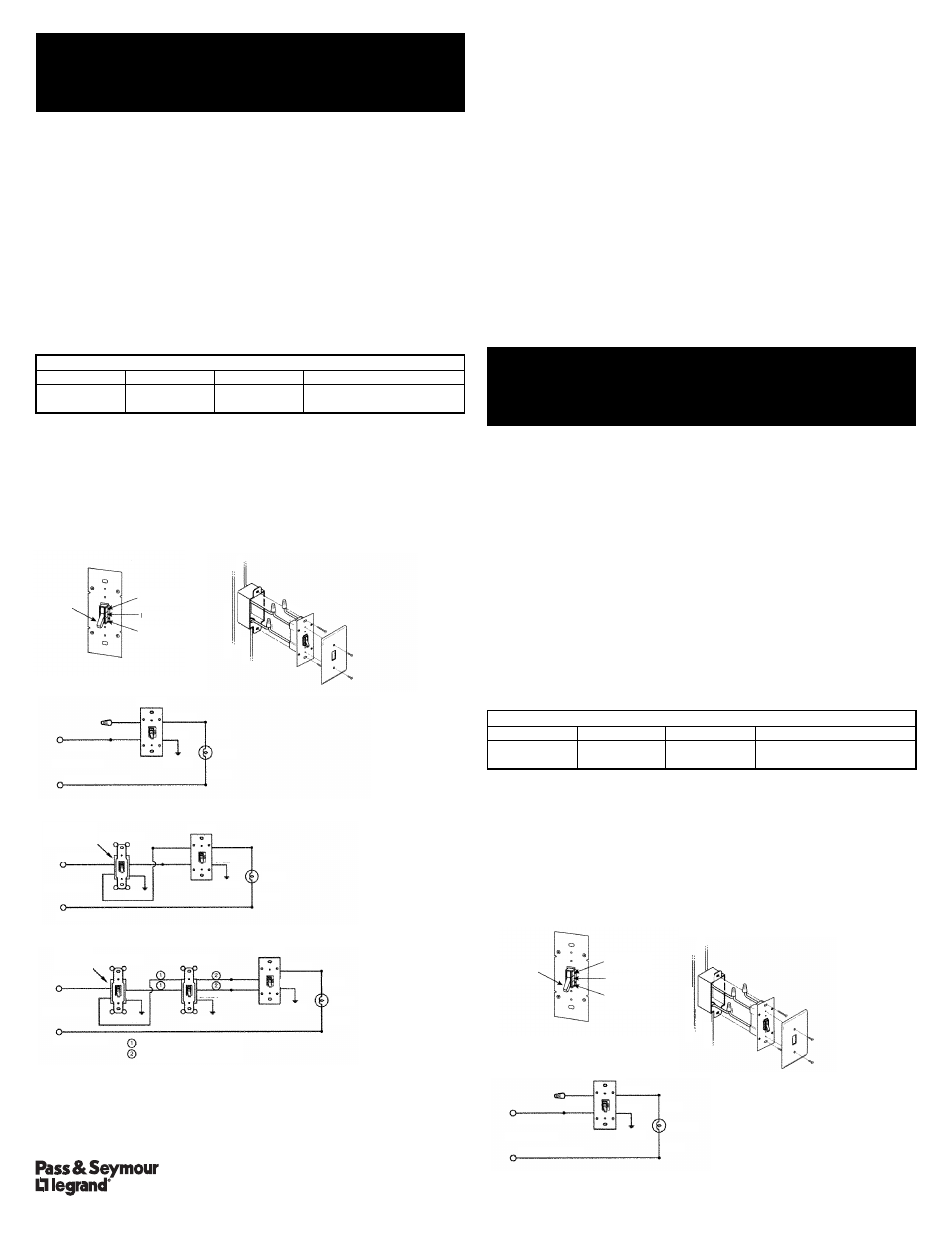
WIRING DIAGRAMS
Dimmer Parts Diagram
Wiring Diagram
Single Control Application
Two Location Control Application
Three Location Control Application
CAUTION
In 3-Way Application, dimmer should be wired directly to load as shipped from the factory (small toggle
switch on back of device in UP position). To wire directly to line, flip small toggle switch on back of
device to DOWN position.
NOTE
Control may feel warm to the touch in normal operation
LIMITED THREE YEAR WARRANTY
Pass & Seymour will remedy any defect in workmanship or material in Pass & Seymour products which
may develop under proper and normal use within three years from date of purchase by a consumer:
(1) by repair or replacement, or, at Pass & Seymourʼs option, (2) by return of an amount equal to
consumerʼs purchase price. Such remedy is IN LIEU OF ANY AND ALL EXPRESSED OR IMPLIED
WARRANTIES OF MERCHANTABILITY OR FITNESS FOR A PARTICULAR PURPOSE. Such remedy
by Pass & Seymour does not include or cover cost of labor for removal or reinstallation of the product.
ALL OTHER FURTHER ELEMENTS OF DAMAGE (INCIDENTAL OR CONSEQUENTIAL DAMAGES)
FOR BREACH OF ANY AND ALL EXPRESSED OR IMPLIED WARRANTIES INCLUDING
WARRANTIES OF MERCHANTABILITY OR FITNESS FOR A PARTICULAR PURPOSE ARE
EXCLUDED HEREBY. (Some states do not allow disclaimers or exclusion or limitation of incidental or
consequential damages, so the above disclaimer and limitation or exclusion may not apply to you.) ANY
IMPLIED WARRANTIES INCLUDING WHERE REQUIRED WARRANTIES OF MERCHANTABILITY OR
FITNESS FOR A PARTICULAR PURPOSE SHALL BE LIMITED TO THE THREE YEARS PERIOD SET
FORTH ABOVE. (Some states do not allow limitations on how long an implied warranty lasts, so the
above limitation may not apply to you.)
To insure safety, all repairs to Pass & Seymour products must be made by Pass & Seymour, or under its
specific direction. Procedure to obtain performance of any warranty obligation is as follows: (1) Contact
Pass & Seymour, Syracuse, New York 13221, for instructions concerning return or repair; (2) return the
product to Pass & Seymour, postage paid, with your name and address and a written description of the
installation or use of the Pass & Seymour product, and the observed defects or failure to operate, or other
claimed basis for dissatisfaction.
This warranty gives you specific legal rights and you may also have other rights which vary from state to
state.
This product is covered by one or more of the following U.S. Patents: 4,413,211; 4,430,576; 4,465,956;
4,733,138; 4,792,731; 4,871,893; 4.880,950; 4,988,840; 4,992,709; 5,128,654; 5,189,259; 5,194,858;
and DES 333,124. Other Patents Pending.
We reserve the right to change details of design, materials and finish, in any way that will not alter
installed appearance or reduce function performance.
Lire et conserver ces instructions.
Schémas de câblage et dʼinstallation ci-dessous
Pour utilisation avec les modèles : T600E, T1000E
ATTENTION
:
Pour éviter toute surchauffe et endommagement éventuel de lʼéquipement, ne pas installer ce dispositif
pour contrôler une prise, un tube fluorescent ou un appareil ménager équipé dʼun moteur
ou alimenté par un transformateur.
AVIS : Nʼutiliser que des fils en cuivre avec ces dispositifs.
Ce contrôleur est conçu pour être installé dans une boîte électrique en métal ou en plastique
(polymère) homologuée par UL.
Installation
1. Couper lʼalimentation du circuit en retirant le fusible ou en ouvrant les disjoncteurs avant
de commencer lʼinstallation.
2. Retirer la plaque murale et lʼinterrupteur existants.
3. Dénuder les fils sur 13 mm (1/2 po) pour les fils de calibre 14 ou plus, ou 16 mm (5/8 po)
pour les fils de calibre 16 ou moins.
4. Installer le gradateur comme illustré en utilisant les connecteurs fournis.
5. Installer le gradateur dans la boîte murale.
6. Remonter la plaque murale.
7. Placer lʼinterrupteur en position ARRÊT avant de remettre le circuit sous tension.
CHARGE MAXIMALE PAR GRADATEUR POUR INSTALLATION MULTIPLE
N° CAT.
SIMPLE
DOUBLE
Plus de DEUX
T600E
600W
500W
400W
T1000E
1000W
800W
700W
FONCTIONNEMENT
1. Pour allumer :
Unipolaire : Mettre la bascule en position haute.
Tripolaire : Mettre la bascule en position haute ou basse pour que la DEL sʼéteigne et/ou que
la lumière sʼallume.
2. Effleurer la plaque tactile supérieure ou inférieure pour ajuster lʼintensité lumineuse.
3. Pour éteindre :
Unipolaire : Mettre la bascule en position basse.
Tripolaire : Mettre la bascule en position haute ou basse pour que la DEL sʼallume et/ou que
la lumière sʼéteigne.
SCHÉMAS DE CÂBLAGE
Schéma des pièces du gradateur
Schéma de câblage
Contrôle à partir
dʼun seul emplacement
NEUTRAL
(WHITE)
HOT
TO
LIGHT
BLUE
BLACK
RED
P.O. Box 4822, Syracuse, NY 13221
www.passandseymour.com
Technical Support / Support technique (800) 223-4185
600W & 1000W Electronic Toggle Dimmers
INSTALLATION & OPERATING INSTRUCTIONS
Part No. 340559 Rev. D
85-1206
Gradateurs électroniques à bascule de 600 et 1000 W
INSTRUCTIONS DʼINSTALLATION ET DʼUTILISATION
Pièce n° 340559 Rév. D
85-1206
ON/OFF
Toggle
Upper Touch
Pad
LED
Lower Touch
Pad
120VAC 60 HZ
NEUTRAL (WHITE)
RED
DIMMER
WHITE
LOAD
BLACK
BLACK
HOT (BLACK)
BLUE
GREEN
GROUND
WHITE
LOAD
BLACK
RED
DIMMER
BLACK
BLUE
GREEN
GROUND
RED
DIMMER
BLACK
BLUE
GREEN
GROUND
WHITE
LOAD
BLACK
GREEN
GROUND
GREEN
GROUND
GREEN
GROUND
4-WAY SWITCH
3-WAY SWITCH
3-WAY SWITCH
120VAC 60 HZ
NEUTRAL (WHITE)
HOT (BLACK)
120VAC 60 HZ
NEUTRAL (WHITE)
HOT (BLACK)
COMMON
TERMINAL
(Black Screw)
COMMON
TERMINAL
(Black Screw)
Travelers between switches “IN”
Travelers between switches “OUT”
Plaque tactile
supérieure
DEL
Plaque tactile
inférieure
120 VCA 60 HZ
NEUTRE (BLANC)
ROUGE
GRADATEUR
BLANC
CHARGE
NOIR
NOIR
PHASE (NOIR)
BLEU
VERT
TERRE
NEUTRE
(BLANC)
PHASE
VERS
Lʼ
AMPOULE
BLEU
NOIR
ROUGE