Legrand Wide Slide Series Incandescent Dimmers User Manual
Wide slide series, Serie perilla deslizable ancha, Instrucciones en español
7. Restore power. To change the mini
mum speed, DISCONNECT POWER
FROM CIRCUIT, and remove the
wall plate. Use a small insulated, flat
tipped screwdriver to adjust the trim
pot, which is accessible via the slot
(marked CALIBRATION) provided on
the strap. Turn up to increase the
minimum speed setting. Next, mount
the wall plate back and restore the
power.
NOTE: Never adjust trim pot
when circuit is live.
NOTE: A 0.3A minimum load is required. It is normal for the control to feel
warm during operation. Use a separate neutral wire for each phase of a
multiphase system containing a dimmer, and for high power single phase
applications where flickering is present.
WARRANTIES
Lifetime Warranty. The device you have purchased is warranted under normal
use against defects in workmanship and materials for as long as you own the
device. If the device fails due to manufacturing defect during normal use, return
the device for replacement to the store where purchased or send to:
Pass & Seymour Legrand
50 Boyd Avenue
Syracuse, NY 13209
All requests for replacement must include a dated sales receipt (legible copies
acceptable).
ALL OTHER WARRANTIES, INCLUDING BUT NOT LIMITED TO ANY
WARRANTIES OF MERCHANTABILITY OR FITNESS FOR A PARTICULAR
PURPOSE, ARE LIMITED TO A PERIOD OF TWO YEARS FROM THE
DATE OF PURCHASE. YOUR SOLE AND EXCLUSIVE REMEDY AGAINST
PASS & SEYMOUR LEGRAND UNDER ANY WARRANTY SHALL BE THE
EQUIVALENT REPLACEMENT OF THE DEVICE. IN NO EVENT SHALL ANY
WARRANTY APPLY TO ANY DEFECT ARISING OUT OF ANY ALTERATION
OF THE DEVICE, IMPROPER WIRING, IMPROPER INSTALLATION, MISUSE,
ABNORMAL USE OR NEGLIGENCE. IN NO EVENT SHALL PASS &
SEYMOUR LEGRAND BE LIABLE FOR LOST PROFITS, INDIRECT, SPECIAL,
EXEMPLARY, INCIDENTAL OR CONSEQUENTIAL DAMAGES. Some states
do not allow limitations on how long implied warranties last and do not allow
exclusion or limitation of incidental or consequential damages. Some of the
above limitations or exclusions may not apply to every purchaser.
Para ser instalado por electricista certificado u otra persona capacitada.
ADVERTENCIA: Para prevenir una sacudida eléctrica severa o electrocución,
siempre CORTE la electricidad en el panel de servicio antes de instalar esta
unidad, trabajar en el circuito, o cambiar una lámpara.
AVISO: Para reducir el riesgo de recalentamiento y los posibles daños a otro
equipo, no lo instale para controlar un tomacorriente, una lámpara o tubo
fluorescente, o un electrodoméstico alimentado por un transformador. Use
este mando solo con venti ladores que indican que son apropiados para uso
con mandos de velocidad de ventiladores de estado sólido.
Cualquier número de ventiladores pueden ser controlados por un solo mando
de velocidad de ventiladores dado que la suma de las tasas de amperaje de
los ventiladores no exija la tasa de amperaje del mando del ventilador.
No conecte al reductor de luz a otra fuente de potencia que no sea solo
120VAC, 60Hz.
Solo utilice cables de cobre.
Nota: Puede entrar yeso, polvo o pintura y dañar este dispositivo. No
instalar este dispositivo hasta después de haber instalado y pintado la
pared.
INSTRUCCIONES:
1. Si se suministró un kit de cambio de color, y se desea un color diferente, vea
el Procedimiento de Cambio de Color; de lo contrario, proceda al paso #2.
2. Corte la electricidad al circuito en el panel quitando el fusible o APAGANDO
el interruptor automático antes de la instalación.
3. Quite la chapa de pared y los tornillos de montura de chucho, hale el
chucho existente de la caja embutida en la pared.
4. Desconecte el chucho existente del circuito. Instalación de tres direcciones:
Identifique el cabe “COMÚN” (el cable conectado al la terminal marcada
“común – common” o la terminal colorada con un color singular). Para
instalación “nueva” identifique el cable conectado al la fuente de potencia
o a la carga.
5. Conecte el controlador de velocidad del ventilador como mostrado en el
diagrama de instalación utilizando alambre trenzado o sólido #12 o #14 AWG
de cobre. Pele el alambre utilizando la guÌa en la parte trasera del aparato.
INSTRUCCIONES DE INSTALACIÓN
Serie Perilla Deslizable Ancha
CONTROLES DE VELOCIDAD DEL VENTILADOR
INSTRUCCIONES EN ESPAÑOL
L E A Y G U A R D E E S T A S I N S T R U C C I O N E S
To be installed by a certified electrician or other qualified person.
WARNING – To prevent severe shock or electrocution, always turn power OFF at the
service panel before installing this unit, working on the circuit, or changing a lamp.
CAUTION – To reduce the risk of overheating and possible damage to other
equipment, do not install to control a receptacle, a fluorescent light or bulb,
or a transformersupplied appliance. Use this control only with fans that are
marked as suitable for use with solidstate fan speed controls.
Any number of fans may be controlled by a single fan speed control provided
the sum amperage rating of the fans does not exceed the amperage rating of
the fan control.
Do not connect fan control to power source other than 120VAC, 60 Hz only.
Use copper wire only.
Note: Sheet rock, dust and paint can enter and damage this device. This
device should be installed after sheet rocking and painting are completed
COLOR CHANGE PROCEDURE/PROCÉDURE DE CHANGEMENT DE
COULEUR/PROCEDIMIENTO DE CAMBIO DE COLOR
DIRECTIONS
1. If a color change kit was provided, and a different color is desired, see the
Color Change Procedure, if not proceed to step #2.
2. Disconnect power to circuit at the panel by removing fuse or turning circuit
breakers OFF before installing.
3. Remove wall plate and switch mounting screws, pull existing switch from
wall box.
4. Disconnect existing switch from circuit. 3way installation: Identify the
“Common” wire (wire connected to the terminal marked common or odd
colored terminal). For “new” installation identify wire connected to power
source or to the load.
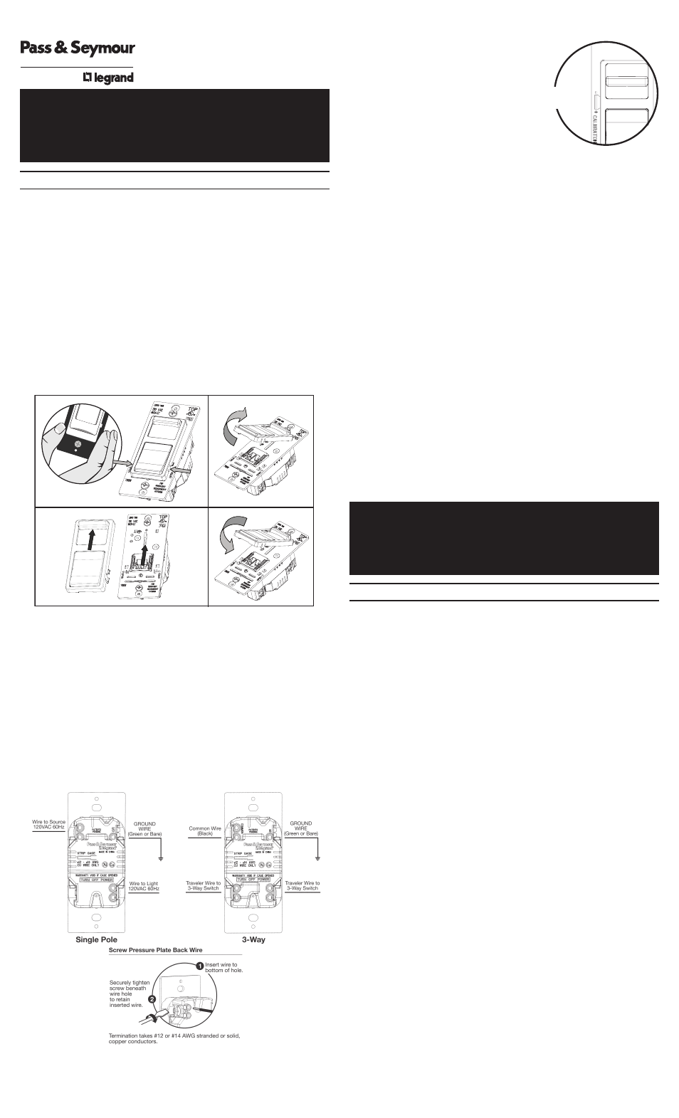
5. Connect fan speed control as shown in the installation diagram using #12
or #14 AWG stranded or solid copper conductors. Strip wire using gauge
on back of device.
INSTALLATION DIAGRAM FOR SPEED CONTROLS
6. Install fan speed control in wall box, with word ‘TOP’ on the strap right side
up, using mounting screws provided.
Trim
Potentiometer
1.
2.
3.
4.
INSTALLATION INSTRUCTIONS
Wide Slide Series
FAN SPEED CONTROLS
R E A D A N D S A V E T H E S E I N S T R U C T I O N S !