Legrand LSDC163PBKV User Manual
Instructions en français, Dual slide de-hummer
INSTALLATION INSTRUCTIONS
DUAL SLIDE DE-HUMMER
®
FAN CONTROL AND
INCANDESCENT LIGHT DIMMER WITH PRESET
R E A D A N D S A V E T H E S E I N S T R U C T I O N S !
DE-HUMMER
®
FAN CONTROL AND DIMMER
Installation Instructions for New Construction
Single Pole/3-Way 3 Speed De-Hummer
®
Fan Control: 1.6A, 120VAC, 60Hz
300W Single Pole/3-Way Incandescent Dimmer: 120VAC, 60Hz
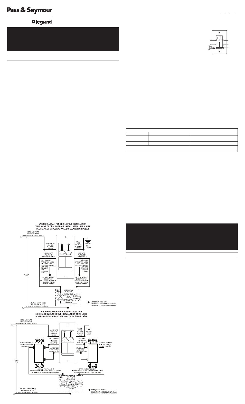
WIRING AND INSTALLATION DIAGRAMS BELOW
CAUTION: To be installed by a certified electrician or other qualified person. To
prevent severe shock or electrocution, always turn power OFF at the service
panel before installing this unit. Use only copper or copper clad wire with this
device. Use with paddle fans only. Use with incandescent lamps only. Do not
exceed the maximum wattage of the dimmer or the maximum amperage of the
fan control. To reduce the risk of overheating and possible damage to other
equipment, do not install to control a receptacle, a fluorescent lighting fixture,
a motor operated appliance, or a transformer supplied appliance.
GANGING MULTIPLE DIMMERS – This Control may be ganged together
without derating. Fan speeds vary by manufacturer. Some fans may turn too
slowly at the lowest setting. The light dimmer requires a minimum 25 watt load
for proper operation.
Attention: In most retrofit applications, it is necessary to add an additional wire
from the Control to the Fan. This is necessary to achieve independent control
and maximize the versatility of the Fan & Light. The additional wire should not
be confused with the Neutral wire, usually White, nor the Ground wire, normally
Bare or Green. Retrofit installations should be done only by a certified
electrician.
INSTALLATION INSTRUCTIONS:
1. Prior to installation, set the fan to its highest speed and the light to its
brightest setting.
2. Disconnect power to the circuit.
3. Strip installed wires per the chart below.
4. Connect the Control’s wires to installed wiring as shown in the Wiring
Diagram using the wire connectors provided.
5. Mount the Control to outlet box using mounting screws provided.
6. Attach the wall plate to Control using colored mounting screws provided.
7. Set the fan control to its OFF (lowest) position.
8. Restore power to the circuit.
9. Test the installation by operating the Control according to the Operating
Instructions below. Be sure the fan starts and does not stall in any of the
ON positions. The best operation may be obtained by starting the fan in the
highest setting and then moving the control to the desired speed. Do not
allow the fan to remain stalled. This may overheat the fan. DO NOT USE
THE PULL CHAIN TO CONTROL THE FAN SPEED AFTER INSTALLATION
OF THIS CONTROL.
OPERATING INSTRUCTIONS:
Toggle the light or fan switch provided to turn the respective unit ON or OFF.
To change lighting level or fan speed, slide the respective knob up or down
until desired level is reached.
Use only copper or copper clad wire with this device.
LIGHT MODULE:
(Sold separately, Catalog #TM8LMCC)
Transform in minutes a standard dimmer into an
illuminated dimmer (ON when light is OFF) –
allows the dimmer to be found in the dark.
Average 20-year life expectancy.
No wiring – quick snap-in installation.
IMPORTANT NOTES:
1. All Fan Speed Controls can be damaged by improper wiring. Check for
short circuits prior to installing the fan speed control.
Procedure for short circuit check:
a. Disconnect power to circuit by removing fuse or turn circuit breakers
OFF.
b. Install a switch instead of the fan speed control. Turn the switch to the
“ON” position.
c. If the fan fails to turn ON and OFF with the switch, the wiring may be
incorrect.
d. Correct wiring, if necessary and retest.
e. Install the fan speed control only after the fan operates properly with the
switch.
2. Protect from dirt and dust. The Fan Speed Control can be damaged from
contaminants encountered during the construction process. The control
should not be installed until the construction process is complete.
Any Fan Speed Control damage due to improper installation is not
covered under warranty.
LIFETIME WARRANTY
The device you have purchased is warranted under normal use against defects in workman-
ship and materials for as long as you own the device. If the device fails due to manufactur-
ing defect during normal use, return the device for replacement to the store where purchased
or send to:
Pass & Seymour Legrand Consumer Division
50 Boyd Avenue, Syracuse, NY 13209
All requests for replacement must include a dated sales receipt (legible copies acceptable).
ALL OTHER WARRANTIES, INCLUDING BUT NOT LIMITED TO ANY WARRANTIES OF
MERCHANTABILITY OR FITNESS FOR A PARTICULAR PURPOSE, ARE LIMITED TO A
PERIOD OF TWO YEARS FROM THE DATE OF PURCHASE. YOUR SOLE AND EXCLU-
SIVE REMEDY AGAINST PASS & SEYMOUR LEGRAND UNDER ANY WARRANTY SHALL
BE THE EQUIVALENT REPLACEMENT OF THE DEVICE. IN NO EVENT SHALL ANY WAR-
RANTY APPLY TO ANY DEFECT ARISING OUT OF ANY ALTERATION OF THE DEVICE,
IMPROPER WIRING, IMPROPER INSTALLATION, MISUSE, ABNORMAL USE OR NEGLI-
GENCE. IN NO EVENT SHALL PASS & SEYMOUR LEGRAND BE LIABLE FOR LOST
PROFITS, INDIRECT, SPECIAL, EXEMPLARY, INCIDENTAL OR CONSEQUENTIAL DAM-
AGES. Some states do not allow limitations on how long implied warranties last and do not
allow exclusion or limitation of incidental or consequential damages. Some of the above
limitations or exclusions may not apply to every purchaser.
GRADATEUR ET CONTRÔLEUR DE VENTILATEUR DE-HUMMER
®
Instructions d’installation pour les nouvelles constructions
Contrôleur de ventilateur De-Hummer
®
3 vitesses, unipolaire/3 voies :
1,6 A, 120 VCA, 60 Hz
Gradateur unipolaire/3 voies pour lampes incandescentes de 300 W :
120 VCA, 60 Hz
MISE EN GARDE : Doit être installé par un électricien certifié ou une autre
personne qualifiée. Pour éviter tout choc électrique ou une électrocution,
toujours couper l’électricité au niveau du panneau d’alimentation avant
d’installer ce dispositif. N’utiliser ce dispositif qu’avec des fils en cuivre ou
cuivrés. N’utiliser qu’avec des ventilateurs à pales. N’utiliser qu’avec des
lampes incandescentes. Ne pas dépasser la capacité maximale du gradateur
ou l’ampérage maximal du contrôleur. Pour éviter toute surchauffe et
endommagement éventuel des autres appareils, ne pas utiliser pour contrôler
une prise, une lampe ou un tube fluorescent, ou encore un appareil ménager
équipé d’un moteur ou alimenté par un transformateur.
GROUPEMENT DE PLUSIEURS GRADATEURS – Ce contrôleur peut être
combiné à d’autres dispositifs sans modifier sa puissance nominale. La vitesse
des ventilateurs varie selon le fabricant. Certains ventilateurs peuvent tourner
trop lentement dans la position la plus lente. Le gradateur doit avoir une charge
de 25 watts minimum pour fonctionner correctement.
Attention : Dans la plupart des applications de mise à niveau, il est nécessaire
d’ajouter un fil entre le contrôleur et le ventilateur. Ceci est nécessaire pour
assurer un contrôle indépendant et maximiser la souplesse d’utilisation de la
lampe et du ventilateur. Ce fil supplémentaire ne doit pas être confondu avec
le fil du neutre, habituellement blanc, ou le fil de terre, habituellement nu ou
vert. Les installations de mise à niveau doivent être effectuées par un
électricien certifié uniquement.
INSTRUCTIONS D’INSTALLATION
1. Avant l’installation, régler le ventilateur à sa vitesse la plus élevée et la
lumière à son intensité maximale.
2. Couper l’alimentation du circuit.
3. Dénuder les fils installés selon les indications du tableau ci-dessous.
4. Raccorder les fils du gradateur aux fils installés comme indiqué sur le
Diagramme de câblage en utilisant les connecteurs de fils fournis.
5. Fixer le contrôleur sur la boîte à l’aide des vis de fixation fournies.
INSTRUCTIONS D’INSTALLATION
CONTRÔLEUR DE VENTILATEUR ET GRADATEUR
POUR LAMPES INCANDESCENTES, À DEUX
CURSEURS AVEC PRÉRÉGLAGE
INSTRUCTIONS EN FRANÇAIS
L I R E E T C O N S E R V E R C E S I N S T R U C T I O N S
WIRE CONNECTOR USAGE CHART
CONNECTOR
WIRE COMBINATIONS
WIRE STRIP LENGTH
LARGE
1 #14 + 1 #18
7/16" (11mm) for Solid wire
1/2" (13mm) for Stranded wire
SMALL
1 #18
3/8" (9.5mm) for Solid wire
Strip wires per chart. Align ends. Push wires firmly into connector. Screw connector securely onto
wires. Note: The Control is supplied with #18 wire.
Fan
Speed
Control
Knob
Optional
Light
Module
Light Level
Control
Knob
Fan
Switch
Light
Switch