Legrand LSCLDC163PBK User Manual
Pass & seymour, Instructions en français
No: 341090 – 10/14
Pass & Seymour
®
De-Hummer
®
Fan Control and Dimmer: CFL/LED 150W, 120VAC, 60 Hz; Incandescent 300W, 120VAC, 60 Hz;
Fan Control: 1.6A, 120VAC, 60Hz
Gradateur et Contrôleur de Ventilateur De-Hummer
®
: CFL/LED 150 W, 120 VCA, 60 Hz; Incandescents 300 W,
120 VCA, 60 Hz; Contrôleur de ventilateur 1,6 A, 120 VCA, 60 Hz
De-Hummer
®
Control de Ventilador y Atenuado: CFL/LED 150 W, 120 VCA, 60 Hz; Incandescente 300 W, 120 VCA,
60 Hz; Control de ventilador 1,6 A, 120 VCA, 60 Hz
Installation Instructions • Instructions d’Installation • Instrucciones de Instalación
Catalog Number(s) • Numéro(s) de Catalogue • Les Numéros de Catálgo: LSCLDC163P
Country of Origin: Made in China • Pays d’origine: Fabriqué en Chine • País de origen: Hecho en China
IMPORTANT NOTES:
1. All Fan Speed Controls can be damaged by improper wiring. Check for short circuits prior to installing the fan
speed control.
Procedure for short circuit check:
a. Disconnect power to circuit by removing fuse or turn circuit breakers OFF.
b. Install a switch instead of the fan speed control. Turn the switch to the “ON” position.
c. If the fan fails to turn ON and OFF with the switch, the wiring may be incorrect.
d. Correct wiring, if necessary and retest.
e. Install the fan speed control only after the fan operates properly with the switch.
2. Protect from dirt and dust. The Fan Speed Control can be damaged from contaminants encountered during the
construction process. The control should not be installed until the construction process is complete.
Any Fan Speed Control damage due to improper installation is not covered under warranty.
Attention: In most retrofit applications, it is necessary to add an additional wire from the Control to the Fan. This
is necessary to achieve independent control and maximize the versatility of the Fan & Light. The additional wire
should not be confused with the Neutral wire, usually White, nor the Ground wire, normally Bare or Green. Retrofit
installations should be done only by a certified electrician.
INSTRUCTIONS:
1. Prior to installation, set the fan to its highest speed and the light to its brightest setting.
2. Disconnect power to the circuit.
3. Strip installed wires per the chart below.
4. Connect the Control’s wires to installed wiring as shown in the Wiring Diagram using the wire connectors provided.
5. Mount the Control to outlet box using mounting screws provided.
6. Attach the wall plate.
7. Set the fan control to its OFF (lowest) position.
8. Restore power to the circuit.
9. Be sure the fan starts and does not stall in any of the ON positions. The best operation may be obtained by
starting the fan in the highest setting and then moving the control to the desired speed. Do not allow the fan to
remain stalled. This may overheat the fan. DO NOT USE THE PULL CHAIN TO CONTROL THE FAN SPEED
AFTER INSTALLATION OF THIS CONTROL.
10. Dimmer may require adjustment to the low end setting to reliably start and/or remove flickering in bulbs. To
adjust, DISCONNECT POWER FROM CIRCUIT, and remove the wall plate. Use a small insulated, flat tipped
screwdriver to adjust the trim pot wheel, which is accessible via the slot (marked “CALIBRATION”) provided on
the strap (Figure 1). Turn the wheel
downwards to increase the minimum light intensity setting and turn the
wheel
upwards to decrease light intensity. Next, install the wall plate, restore the power and test. Repeat above
as necessary.
Note: Never adjust trim pot when circuit is live.
WIRE CONNECTOR USAGE CHART
CONNECTOR
WIRE COMBINATIONS
WIRE STRIP LENGTH
LARGE
1 #14 + 1 #18
7/16" (11mm) for Solid wire
1/2" (13mm) for Stranded wire
SMALL
1 #18
3/8" (9.5mm) for Solid wire
Strip wires per chart. Align ends. Push wires firmly into connector. Screw connector securely onto wires.
Note: The Control is supplied with #18 wire.
Note: It is normal for the dimmer to feel warm during operation. Use a separate neutral wire
for each phase of a multiphase system containing a dimmer, and for high power single phase
applications where flickering is present.
Any combination of dimmers and other devices may be ganged together.
OPERATING INSTRUCTIONS:
Toggle the light or fan switch provided to turn the respective unit
ON or OFF.
To change lighting level or fan speed, slide the respective knob up or down until
desired level is reached.
Use only copper or copper clad wire with this device.
LIGHT MODULE: (Sold separately, Catalog #TM8LMCC)
Transform in minutes a standard dimmer into an illuminated dimmer
(ON when light is OFF) – allows the dimmer to be found in the dark.
Average 20-year life expectancy.
No wiring – quick snap-in installation.
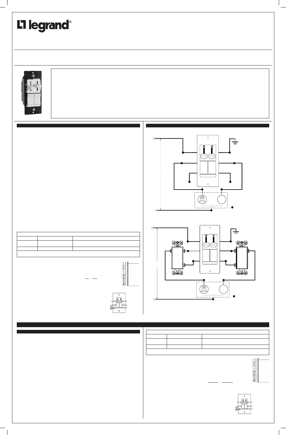
INSTALLATION DIAGRAM
WIRING DIAGRAM FOR SINGLE POLE INSTALLATION
120VAC
60Hz
RED WIRE
WITH 3-WAY
LABEL
YELLOW WIRE
WITH 3-WAY
LABEL
YELLOW
WIRE
RED
WIRE
BLACK
WIRE
GREEN
WIRE
GROUND
NEUTRAL (White Wire)
HOT (Black Wire)
CAP WITH WIRE NUT
CAP WITH WIRE NUT
REPRESENTS WIRE NUT
CEILING FAN
WITH
LIGHT
FAN
LIGHT
WIRING DIAGRAM FOR 3-WAY INSTALLATION
NEUTRAL (White Wire)
BLACK
OR
COMMON
RED
WIRE
YELLOW
WIRE
GROUND
BLACK
WIRE
GREEN
WIRE
HOT (Black Wire)
120VAC
60Hz
BLACK
OR
COMMON
3-WAY SWITCH FOR LIGHT
3-WAY SWITCH FOR LIGHT
REPRESENTS WIRE NUT
CEILING FAN
WITH
LIGHT
FAN
LIGHT
RED WIRE
WITH
3-WAY LABEL
YELLOW
WIRE WITH
3-WAY LABEL
READ AND SAVE THESE INSTRUCTIONS
To be installed by a certified electrician or other qualified person.
WARNING – To prevent severe shock or electrocution, always turn power
off at the service panel before installing this unit, working on the circuit,
or changing a lamp.
CAUTION: To reduce the risk of overheating and possible damage to
other equipment:
• Do not install dimmer to control a receptacle, a motor-operated appliance
or a transformer-supplied appliance.
• Use only with incandescent or compatible dimmable CFL/LED bulbs
which screw into conventional incandescent lamp sockets (compatible
bulbs listed at www.legrand.us).
Connect to 120VAC, 60 Hz power source only.
A minimum load of 10W is recommended for optimal operation of
the dimmer.
Use copper wire only.
LIRE ET CONSERVER CES INSTRUCTIONS
Doit être installé par un électricien certifié ou une autre personne qualifiée.
AVERTISSEMENT – Pour éviter tout choc électrique ou une électrocution,
toujours couper l’électricité au niveau du panneau d’alimentation avant
d’installer cette unité, de travailler sur le circuit électrique ou de changer
une lampe.
ATTENTION : Pour réduire le risque de surchauffe ou d’endommagement
d’autres pièces d’équipement :
• Ne pas installer un gradateur pour contrôler une prise électrique, ou un
appareil ménager équipé d’un moteur ou alimenté par un transformateur.
• À n’utiliser qu’avec des ampoules à incandescence ou variable à
luminosité CFL/LED ampoules compatibles qui se vissent dans
des douilles d’ampoules à incandescence traditionnelles (ampoules
compatibles énumérés à www.legrand.us).
Connecter à une source de 120 VCA, 60 Hz uniquement.
Une charge minimale de 10W est recommandée pour un fonctionnement
optimal du gradateur.
N’utiliser que des fils en cuivre.
LEA Y CONSERVE ESTAS INSTRUCCIONES
Para ser instalado por un electricista certificado o persona competente.
ADVERTENCIA – Para evitar descargas eléctricas serias o electrocución,
antes de instalar, trabajar en el circuito o cambiar una lámpara de este
atenuador apague siempre el suministro eléctrico en el panel de servicio.
PRECAUCIÓN: Para reducir el riesgo de sobrecalentamiento y posibles
daños a otros equipos:
• No instale un atenuador para controlar un tomacorriente, un
electrodoméstico que funciona con motor o un electrodoméstico con
transformador.
• Utilícese solamente con bombillas incandescentes CFL o LED
atenuables que se atornillan en portalámparas incandescentes
convencionales (bombillas compatibles enumerados en
www.legrand.us).
Conecte solamente a un suministro eléctrico de 120 VAC, 60 Hz.
Una carga minima de 10W se recomienda para un funcionamiento óptimo
del atenuador.
Utilice únicamente alambres de cobre.
Figure 1
Fan Speed
Control
Knob
Optional
Light Module
Light Level
Control Knob
Fan Switch
Light Switch
INSTRUCTIONS EN FRANÇAIS
REMARQUES IMPORTANTES :
Attention : Dans la plupart des applications de mise à niveau, il est nécessaire d’ajouter un fil entre le contrôleur
et le ventilateur. Ceci est nécessaire pour assurer un contrôle indépendant et maximiser la souplesse d’utilisation
de la lampe et du ventilateur. Ce fil supplémentaire ne doit pas être confondu avec le fil du neutre, habituellement
blanc, ou le fil de terre, habituellement nu ou vert. Les installations de mise à niveau doivent être effectuées par un
électricien certifié uniquement.
INSTRUCTIONS :
1. Avant l’installation, régler le ventilateur à sa vitesse la plus élevée et la lumière à son intensité maximale.
2. Couper l’alimentation du circuit.
3. Dénuder les fils installés selon les indications du tableau ci-dessous.
4. Raccorder les fils du gradateur aux fils installés comme indiqué sur le Diagramme de câblage en utilisant les
connecteurs de fils fournis.
5. Fixer le contrôleur sur la boîte à l’aide des vis de fixation fournies.
6. Fixer la plaque murale.
7. Régler le contrôleur du ventilateur sur sa position la plus basse (OFF/ARRÊT).
8. Remettre le circuit sous tension.
9. S’assurer que le ventilateur démarre et ne s’arrête dans aucune des positions ON (MARCHE). Pour assurer
le meilleur fonctionnement, il peut s’avérer utile de démarrer le ventilateur à sa position la plus élevée, puis de
réduire sa vitesse jusqu’à la valeur désirée. Ne pas laisser le ventilateur en position « calée ». Ceci pourrait faire
surchauffer le ventilateur. NE PAS UTILISER LA CHAÎNE POUR CONTRÔLER LA VITESSE DU VENTILATEUR
APRÈS L’INSTALLATION DE CE CONTRÔLEUR.
10. Le gradateur peut avoir à être réglé aux faibles intensités pour que certaines lampes s’allument correctement et/
ou ne clignotent pas. Pour cela, COUPER L’ALIMENTATION DU CIRCUIT et retirer la plaque murale. Utiliser
un petit tournevis plat isolé pour régler le potentiomètre qui est accessible à travers la fente (« CALIBRATION »)
située sur la bande (Figure 1). Tourner la mollette
vers le bas pour augmenter le réglage de l’intensité
lumineuse minimale et tourner la mollette
vers le haut pour réduire l’intensité lumineuse. Ensuite, remonter
la plaque murale, remettre sous tension et tester. Répéter les étapes ci-dessus au besoin.
Remarque : ne
jamais régler le potentiomètre si le circuit est sous tension.
TABLEAU D’UTILISATION DES CONNECTEURS DE FILS
CONNECTEUR
COMBINAISONS DE FILS
LONGUEUR DE DÉNUDAGE DES FILS
GROS
1 #14 + 1 #18
7/16 po (11 mm) pour fil massif
1/2 po (13 mm) pour fil torsadé
PETIT
1 #18
3/8 po (9,5 mm) pour fil massif
Dénuder les fils selon les indications du tableau. Aligner les extrémités. Enfoncer les fils fermement dans le
connecteur. Bien visser le connecteur sur les fils. Remarque : Le contrôleur est fourni avec des fils #18.
Remarque : Il est normal que le gradateur soit tiède au toucher en cours de
fonctionnement. Utiliser un neutre séparé pour chaque phase d’un système multiphasé
contenant un gradateur, et pour les applications monophasées à forte puissance lorsqu’il
existe un scintillement.
N’importe quelle combinaison de gradateurs et d’autres dispositifs peuvent être
installés ensemble.
INSTRUCTIONS D’UTILISATION
Basculer l’interrupteur de la lumière ou du ventilateur pour
l’allumer ou l’éteindre.
Pour modifier l’intensité lumineuse ou la vitesse du ventilateur, faire glisser le curseur
correspondant jusqu’au niveau souhaité.
N’utiliser ce dispositif qu’avec des fils en cuivre ou cuivrés.
MODULE LUMINEUX : (vendu séparément,
n° de catalogue TM8LMCC)
Permet de transformer en quelques minutes un gradateur standard
en un gradateur lumineux (
ALLUMÉ lorsque la lumière est
ÉTEINTE) – Permet de trouver le gradateur dans le noir.
Durée de vie moyenne : 20 ans
Pas de câblage – Installation rapide par enfichage
Figure 1
Bouton
du contrôleur
de vitesse
du ventilateur
Optionnel module
lumineux
Bouton du
gradateur
d’intensité
lumineuse
Interrupteur
du ventilateur
Interrupteur
de la lumière
341090_revB_Dimmers IS_11x17.indd 1
10/6/14 4:13 PM