Legrand TDDH163PBK User Manual
Fan speed control, Control de velocidad de ventilador, Toggle preset de-hummer installation instructions
READ AND SAVE THESE INSTRUCTIONS,
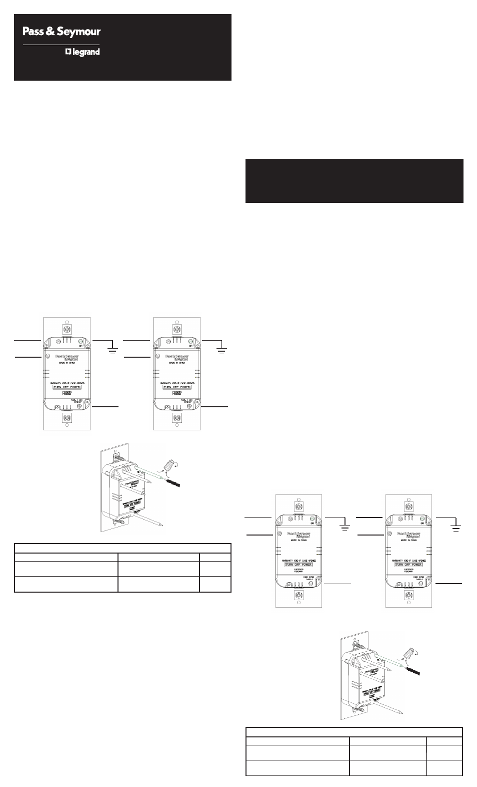
WIRING AND INSTALLATION DIAGRAMS
To be installed by a certified electrician or other qualified person.
This Fan Speed Control is to be used only with ceiling paddle fans.
CAUTION: Due to varying standards by fan manufacturers, the speeds on this
control may vary on all settings. Some fans may turn too fast on high; others
may turn too slowly at the lowest setting of the speed control.
To avoid overheating and possible damage to other equipment do not install
this device to control a receptacle, a fluorescent lighting fixture or bulb, or a
transformer supplied appliance.
Do not use to control a fan and light that can be operated by same switch.
EASY TO INSTALL
Directions:
1. PRIOR TO INSTALLATION, set fan pull chain to its highest speed (be sure fan
is operating at full speed before disconnecting power).
2. Disconnect power to circuit by removing fuse or turning circuit breakers to
OFF before installing.
3. Remove existing wall plate and switch.
4. Connect fan control, as shown in the wiring and installation diagrams, using
the lead wires provided. Install fan control in wall box, with the word “TOP”
on the metal strap right side up, using the mounting screws provided.
5. Fasten fan control to wall box with mounting screws provided.
6. Attach wall plate.
7. Set fan control to OFF position. See Operating Instructions.
(See below)
8. Restore power and test. Be sure to check that fan does not stall in any of the
ON positions. Do not allow fan to remain in “stalled position.” DO NOT USE
PULL CHAIN AFTER INSTALLATION OF FAN CONTROL.
WIRING DIAGRAM
OPERATING INSTRUCTIONS:
1. Use paddle (conventional switch) to turn unit ON or OFF.
2. To change fan speed rotate dial to select desired level.
NOTE: Control may feel warm to the touch in normal operation.
This control is intended for installation in a U.L. Listed metal or (polymeric)
plastic outlet box.
NOTICE:
1. Connect only to a single fan. (Do not use on fan/light kit.)
2. Fan must have thermal protection feature. (Do not allow fan to “stall” in
any ON position.)
Use only copper or copper clad wire with this device.
IMPORTANT NOTES:
1. All Fan Speed Controls can be damaged by improper wiring. Check for short
circuits prior to installing the fan speed control.
Procedure for short circuit check:
a. Disconnect power to circuit by removing fuse or turn circuit breakers
OFF.
b. Install a switch instead of the fan speed control. Turn the switch to the
“ON” position.
c. Turn power ON. If the circuit breaker trips, a short is present. If the light
fails to turn ON and OFF with the switch, the wiring may be incorrect.
d. Correct wiring, if necessary and retest.
e. Install the fan speed control only after the fan operates properly with
the switch.
2. Protect from dirt and dust. The Fan Speed Control can be damaged from
contaminates encountered during the construction process. The control
should not be installed until the construction process is complete.
Any Fan Speed Control damage due to improper installation is
not covered under warranty.
LIFETIME WARRANTY
The device you have purchased is warranted under normal use against defects in
workmanship and materials for as long as you own the device. If the device fails due to
manufacturing defect during normal use, return the device for replacement to the store
where purchased or send to: Pass & Seymour Legrand Consumer Division, 50 Boyd
Avenue, Syracuse, NY 13209. All requests for replacement must include a dated sales
receipt (legible copies acceptable). ALL OTHER WARRANTIES, INCLUDING BUT NOT
LIMITED TO ANY WARRANTIES OF MERCHANTABILITY OR FITNESS FOR A PARTICULAR
PURPOSE, ARE LIMITED TO A PERIOD OF TWO YEARS FROM THE DATE OF PURCHASE.
YOUR SOLE AND EXCLUSIVE REMEDY AGAINST PASS & SEYMOUR LEGRAND UNDER ANY
WARRANTY SHALL BE THE EQUIVALENT REPLACEMENT OF THE DEVICE. IN NO EVENT
SHALL ANY WARRANTY APPLY TO ANY DEFECT ARISING OUT OF ANY ALTERATION OF
THE DEVICE, IMPROPER WIRING, IMPROPER INSTALLATION, MISUSE, ABNORMAL USE
OR NEGLIGENCE. IN NO EVENT SHALL PASS & SEYMOUR LEGRAND BE LIABLE FOR
LOST PROFITS, INDIRECT, SPECIAL, EXEMPLARY, INCIDENTAL OR CONSEQUENTIAL
DAMAGES. Some states do not allow limitations on how long implied warranties last and
do not allow exclusion or limitation of incidental or consequential damages. Some of the
above limitations or exclusions may not apply to every purchaser.
LEA Y GUARDE ESTAS INSTRUCCIONES,
DIAGRAMAS DE CABLEADO E INSTALACIÓN
Para ser instalado por un electricista certificado o persona competente.
Este control de velocidad de ventilador sólo debe utilizarse con ventiladores de
aspas para instalación en techo.
PRECAUCIÓN: Debido a las diferentes normas de los fabricantes de ventiladores,
las velocidades en este control podrían variar en todos los valores de graduación.
Algunos ventiladores podrían girar demasiado rápido en el valor alto; otros
podrían girar demasiado lento en el valor más bajo del control de velocidad.
Para evitar el calentamiento excesivo y posibles daños a otros equipos, no instale
este dispositivo para controlar un tomacorriente, una bombilla o artefacto de
iluminación fluorescente, o un electrodoméstico alimentado por transformador.
No utilice para controlar un ventilador y lámpara que puedan ser operados por
el mismo interruptor.
FÁCIL DE INSTALAR
Instrucciones de uso:
1. ANTES DE LA INSTALACIÓN, ajuste la cadena de accionamiento del ventilador
en su velocidad máxima (antes de desconectar el suministro eléctrico,
asegúrese que el ventilador esté funcionando a máxima velocidad).
2. Antes de instalar, desconecte el suministro eléctrico al circuito retirando el
fusible o apagando los cortacircuitos.
3. Quite la placa e interruptor de pared existentes.
4. Conecte el control de ventilador, según se muestra en los diagramas de
cableado e instalación, utilizando los conductores suministrados. Instale
el control de ventilador en la caja de pared, con los tornillos de montaje
suministrados y con la palabra “TOP” impresa en la banda metálica hacia arriba.
5. Sujete el control de ventilador a la caja de pared mediante los tornillos de
montaje suministrados.
6. Fije la placa de pared.
7. Coloque el control de ventilador en la posición OFF. Consulte las instrucciones
de operación. (Ver abajo)
8. Restaure el suministro eléctrico y pruebe. Asegúrese de verificar que el
ventilador no se bloquea en ninguna de las posiciones de ENCENDIDO. NO
permita que el ventilador permanezca en “posición bloqueada”. NO UTILICE
LA CADENA DE ACCIONAMIENTO DESPUÉS DE LA INSTALACIÓN DEL
CONTROL DE VENTILADOR.
DIAGRAMA DE CABLEADO
DIAGRAMA DE INSTALACIÓN
WIRE CONNECTOR USAGE CHART
WIRE COMBINATIONS
STRIP LENGTHS
COLOR
1#14 & 1#16; 1#14 & 2#18; 2, 3#16;
#14–1/2”, #16 & #18–9/16”
ORANGE
1#16 & 1–3#18: 3–5#18; 2#18
1#14 & 1, 2#16; 1#14 & 1, 2#18;
#14 & #16–7/16”,
IVORY
2, 3#16; 2–5#18
#18–1/2”
Do not USE
this wire for
single pole
installation
(Red)
Wire to
Motor/Source
(Black)
Wire to Load
Single Pole
(Red)
Ground Wire
(Green or
Bare)
Single Pole
3-Way
Toggle Preset De-Hummer
Installation Instructions
Fan Speed Control
Single Pole/3-Way
1.6A, 3-Speed De-Hummer 120VAC, 60Hz
Instrucciones de instalación del ventilador De-Hummer preajustado de basculante
Control de Velocidad de Ventilador
Unipolar/3-Vías
De-Hummer 1.6A, 3 Velocidades, 120VCA, 60Hz
TABLA PARA EL USO DE CAPUCHONES
COMBINACIONES DE CABLES
LARGO A PELAR
COLOR
1#14 & 1#16; 1#14 & 2#18; 2, 3#16;
#14–1/2”, #16 & #18–9/16” ANARANjADO
1#16 & 1–3#18: 3–5#18; 2#18
1#14 & 1, 2#16; 1#14 & 1, 2#18;
#14 & #16–7/16”,
MARFIL
2, 3#16; 2–5#18
#18–1/2”
Girar
Turn
Traveler
Wire to
3-Way
Switch
(Red)
Wire to
Source
(Black)
Wire to Load
(Red)
Ground Wire
(Green or
Bare)
No UTILICE
este alambre
para instalación
unipolar
(Rojo)
Alambre hacia el
motor / la fuente
(Negro)
Alambre
de tierra
(Verde o Desnudo)
Unipolar
3 Vías
Cable a Carga
Unipolar
(Rojo)
Alambre
común hacia
interruptor
de 3 vías
(Rojo)
Alambre hacia
fuente
(Negro)
Alambre
de tierra
(Verde o Desnudo)
Cable a Carga
(Rojo)