Legrand HA5202 User Manual
Is-0457 rev. o
INSTRUCTION / INSTALLATION SHEET
TVDI Expander for Unity Integration
Module (P/N HA5202)
IS-0457 Rev. O
301Fulling Mill Road, Suite G
Middletown, PA 17057
Phone (800) 321-2343 / Fax (717) 702-2546
www.onqlegrand.com
©Copyright 2009 by Legrand All Rights Reserved.
Page 1 of 2
1. Introduction
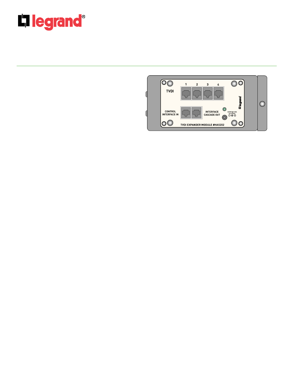
The HA5202 TVDI Expander Module (see Figure 1)
provides the ability to expand beyond two, the
number of TVDI Control Interfaces supported on the
Unity HA6001 Integration Module. Each HA5202
supports four directly connected TVDI Control
Interfaces and is able to be cascaded once, so that
two TVDI Expander Modules may be associated with
one HA6001 Integration Module for support of up to
eight TVDI Control Interfaces. (see Figure 2).
2. Description
• Provides one RJ45 jack for connection to an LCD/TV Display Interface jack on the Unity System Integration
Module.
• Provides one RJ45 jack for cascading up to two total TVDI Expander Modules.
• Provides four RJ45 jacks for connection to individual TV Display Interfaces.
• The first TVDI Expander Module is powered by the attached Integration Module. Any TVDI Expander Modules
connected via the Cascade jack require a 24VDC Power Supply, as power is not passed over the Cascade
connection (see Figure 2).
3. Installation
Installation of the Legrand HA5202 and related components is best accomplished at multiple times during new
construction, at “Rough-in” before the drywall is installed, and at “Trim-out” after the drywall is installed and painted.
IMPORTANT: Read the manuals that are included with all associated Unity products before installation of
any single component. If you are unsure of any of the following installation procedures contact Legrand
Technical Support @ 1-800-321-2343 option 1 or contact a Legrand installer.
A. “Rough-in”
steps:
1. HA5201-xx:
Run a Category 5 cable from each (up to 4) TV Display Interface (HA5201-xx)
location to the enclosure housing the HA5202.
B. “Trim-out”
steps:
NOTE: Make sure that the 24VDC Power Supply is not connected to the HA5202 Module.
1. Install the HA5202/s in the enclosure by first attaching it to the included bracket using the four
corner plungers. Then insert the bracket tabs into the slots on the left of the enclosure and use
the bracket push-pin to secure the HA5202/s to the enclosure.
2. Terminate all Category 5 cables from the TV Display Interfaces with RJ-45 plugs using the T568A
wiring standard, and plug them in to the TVDI RJ45 jacks labeled 1-4 on the HA5202/s.
Figure 1